
If you go through as many amps as I do, you end up with a few things that don’t work and can’t be repaired, or it’s not worth the hassle. If you can buy a working amp for, say, 50 euros, and the blown amp you have is not a rarity and has no sentimental value, what’s the point of paying more than 20 euros for repairs? So I usually sell the amp as faulty or harvest parts I might use and throw away the rest. But sometimes an amp is only half-damaged and you can still save it by turning it into something useful.
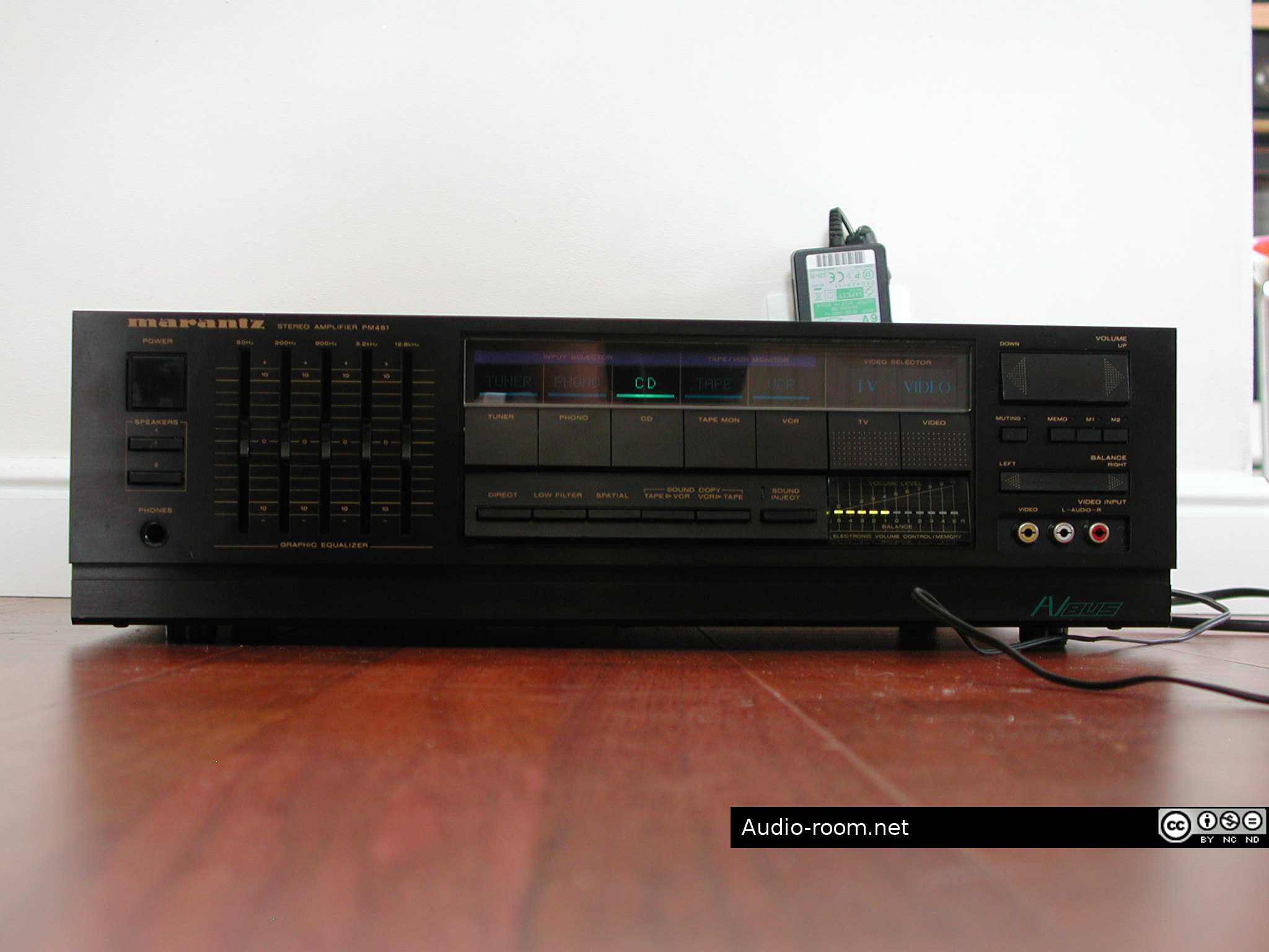
Some time ago I bought a faulty Marantz PM 451 for parts. I needed buttons for another PM 451 that worked fine but was missing 3 buttons and a lamp. I later sold the other PM 451 for more than I paid for both amps, so the parts unit I ended up with was basically a freebie.
I even dropped it at my tech’s, but he couldn’t fix it. He said something was wrong in the preamp section, he couldn’t figure out what exactly. This amp has a lot of unnecessary functions, IC-based volume control with memory, graphic EQ, basically a lot that could go wrong and isn’t worth the effort to fix. But my tech said he had checked the outputs and they seemed fine, power supply seemed OK too.
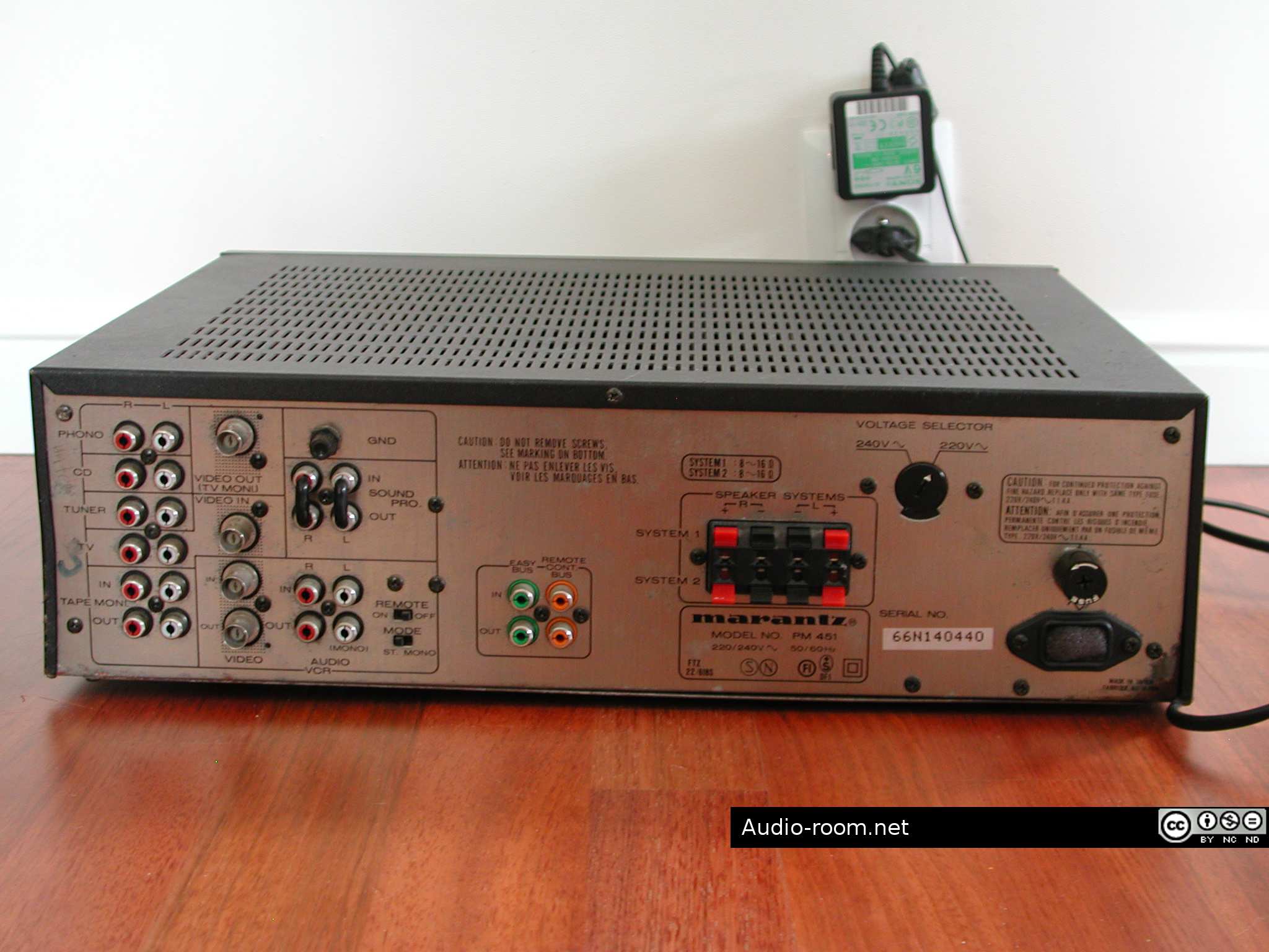
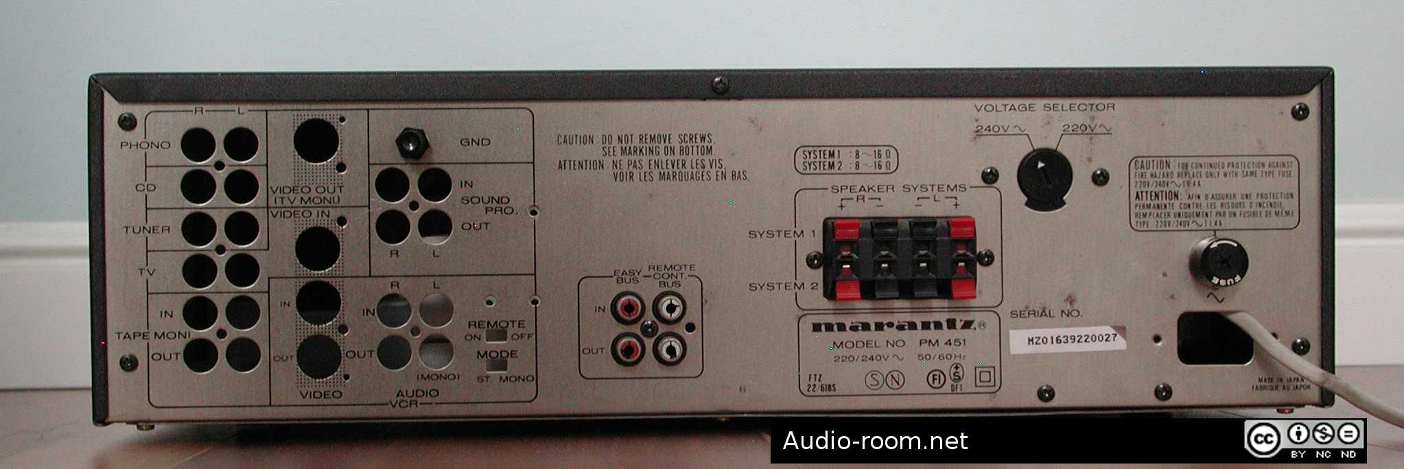
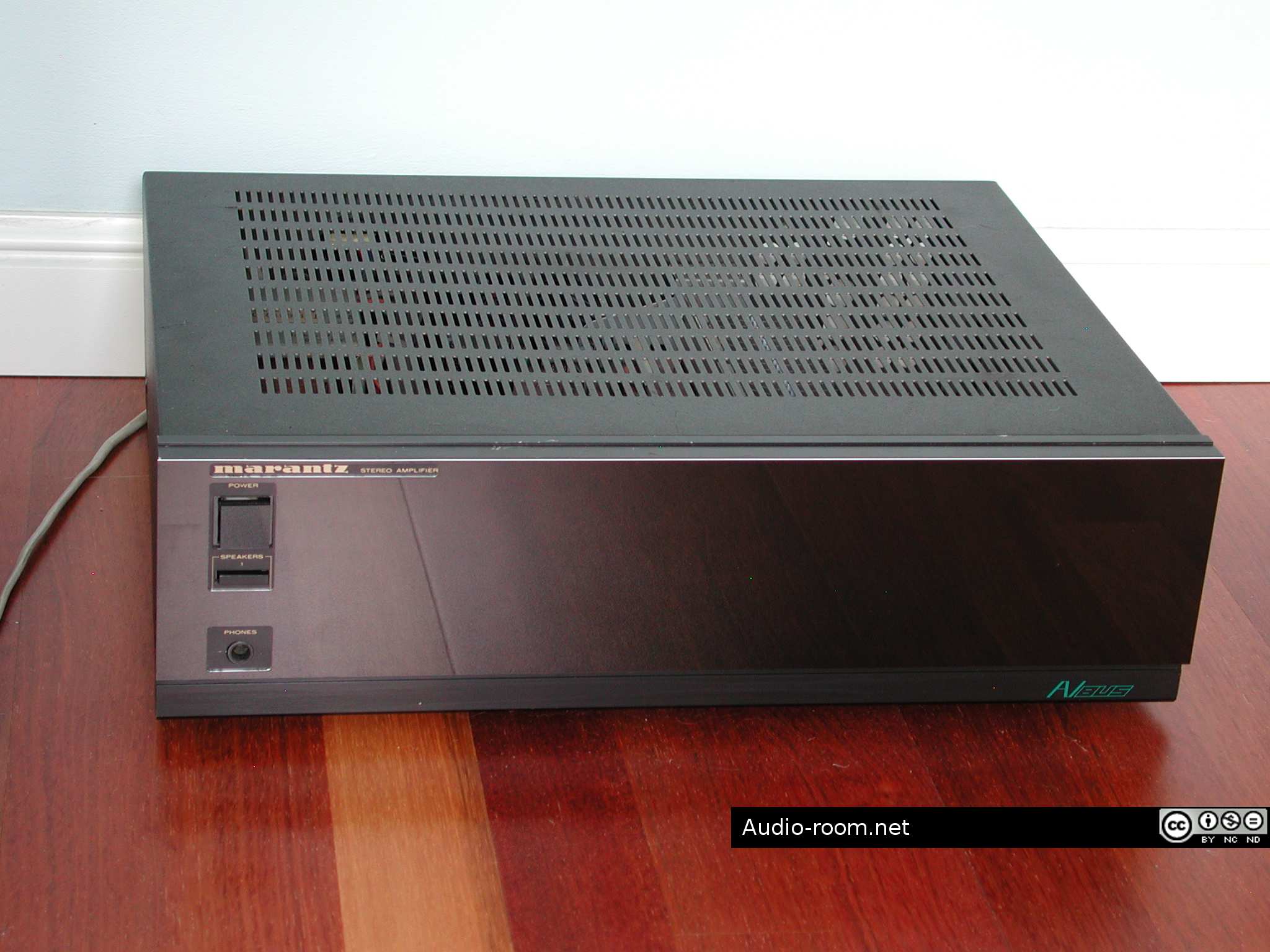
I ended up with an amp that basically isn’t worth fixing, but some of it’s sections appeared to be working fine. And Maranz PM 451 is nothing special, but not a bad amplifier when it works: 2×60 W RMS into 8 ohms, 0,05% THD at rated power and frequency response 10 Hz – 25 kHz. It works fine with 4 ohm speakers, despite the warning on the rear panel.
So I figured: why not get rid of the preamp section and transform it into a power amplifier?
STAGE 1
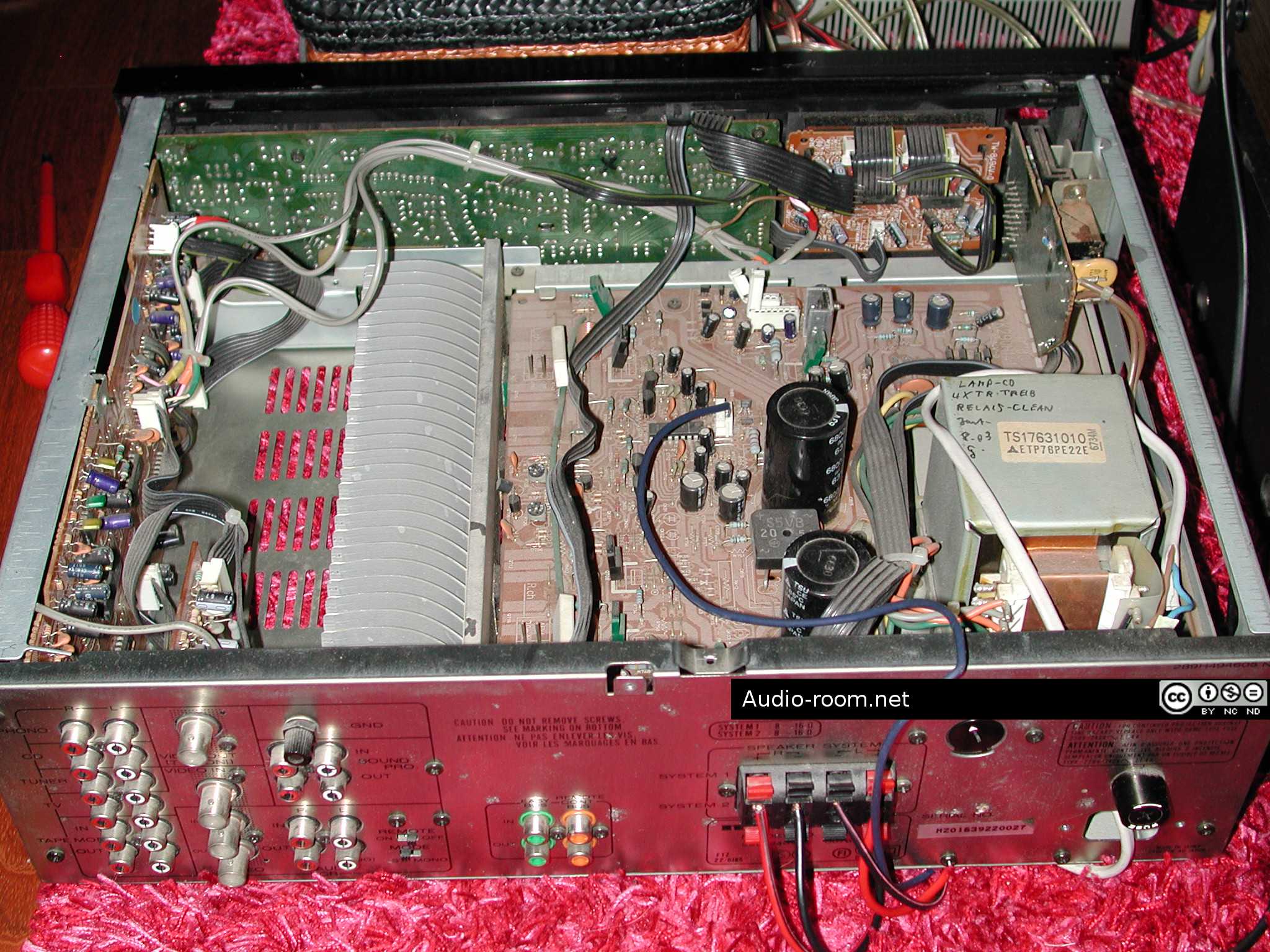
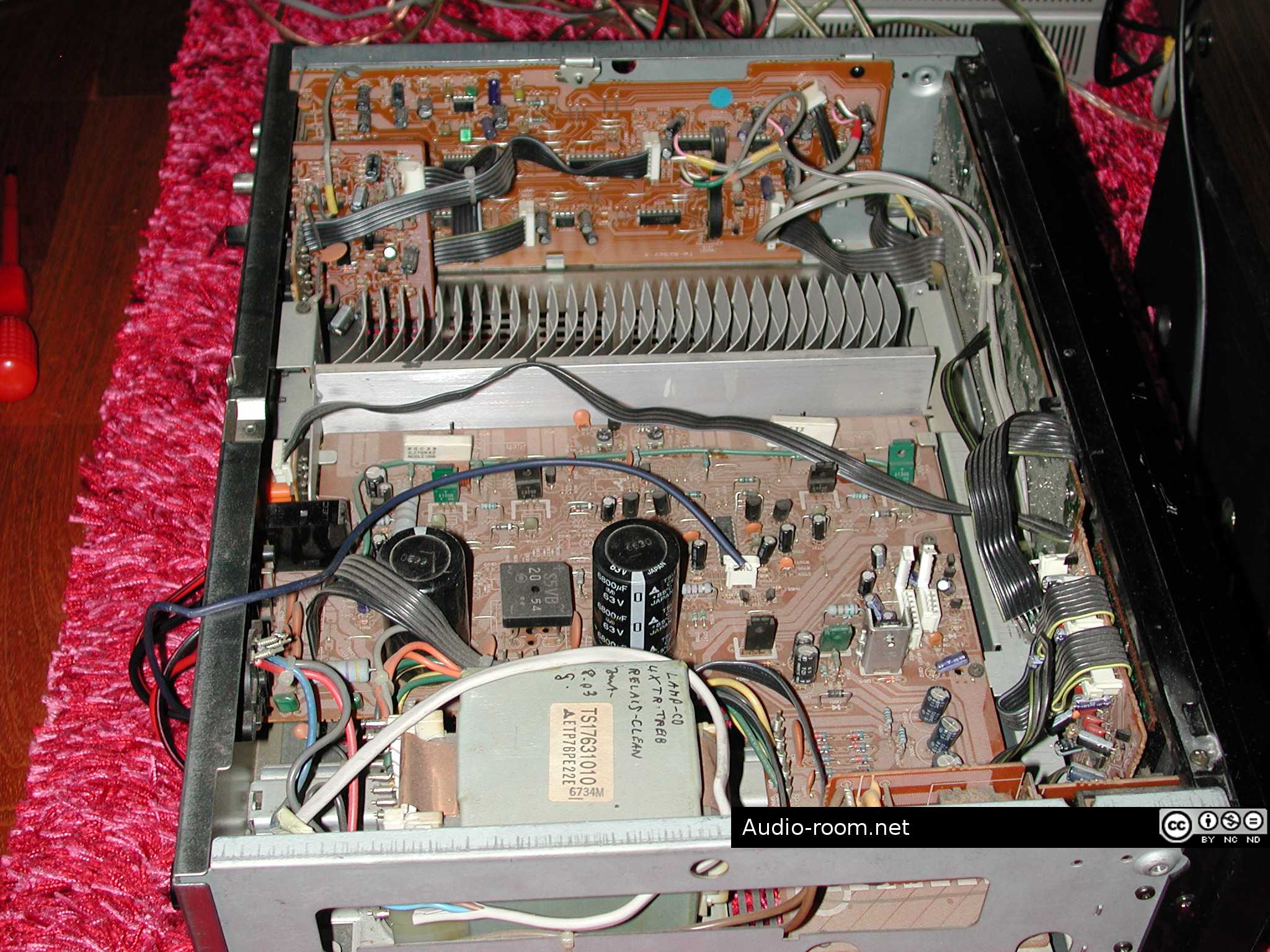
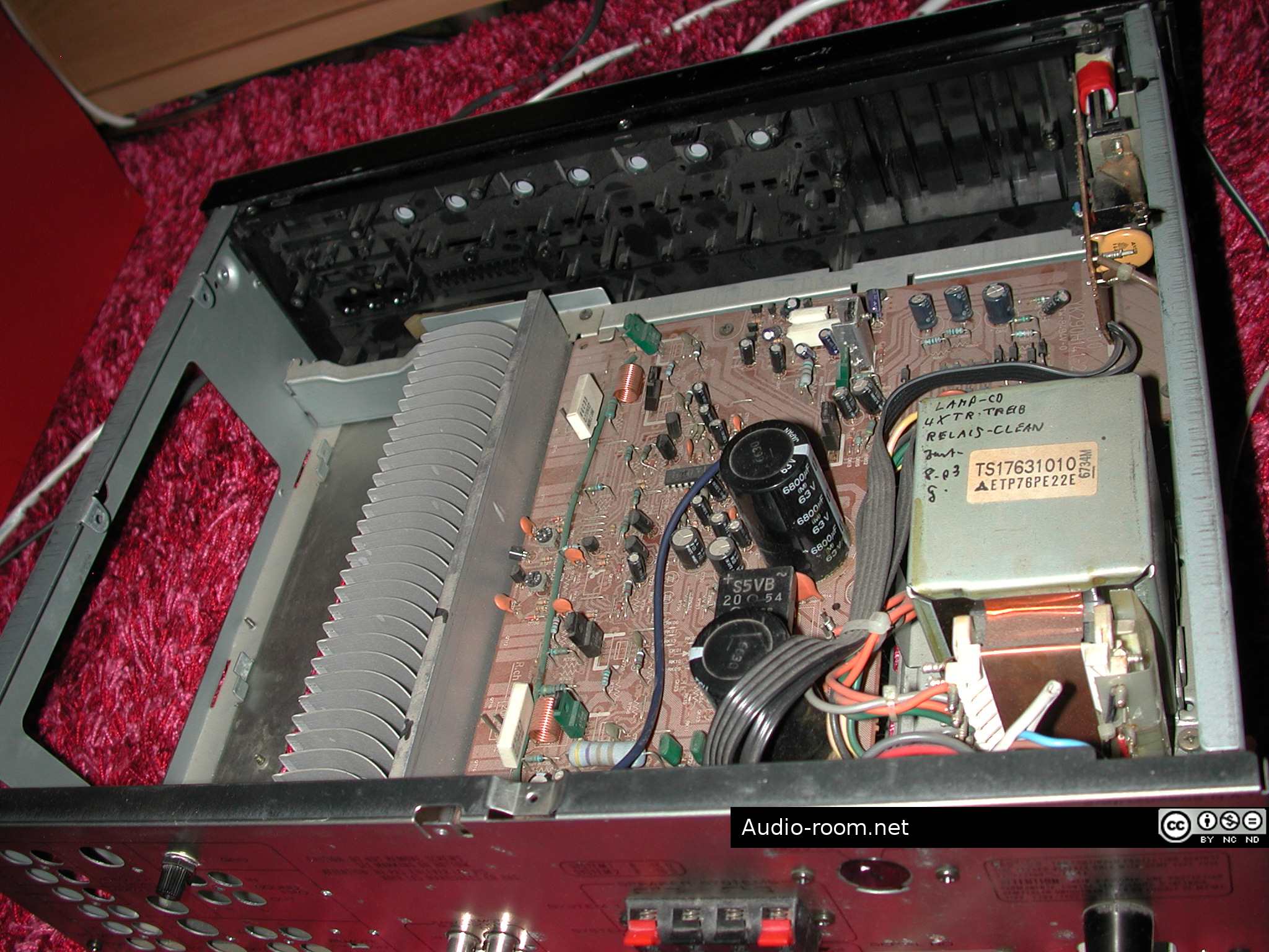
I went through the service manual and figured the power amp section entry point. I measured DC offset of the amp which was not bad (~15 mV on both channels), adjusted DC offset, and connected a wire with headphone plug to the power amp section entry point. I connected a CDP to the other end, through a passive source selector with volume control (QED C.D. COMPARATOR CD9, a very useful box). I checked with a speaker switcher with power monitor first (KENWOOD PM-80, another useful box). It appeared to work, meters showed changing output, then checked DC on terminals with input cranked all the way up – looked fine, DC stayed below 25 mV.
I connected headphones, and it worked! Good, clean sound from both channels. So I tried speakers, fine too, although with not pre-amplified CDP signal I could get only 50-60% of the amp’s rated power. Finally I connected it to a Harman preamplifier, and I got full power. The amplifier worked at its rated power without problems.
I disconnected the entire pre amp section of the Marantz from the power supply and rechecked. All good.
Stage 1 was completed. I had a working power amplifier, but it looked like crap, had a lot of redundant parts, and a makeshift signal wire from headphone cable. But it worked fine and sounded as good as you’d expect of a Marantz power amp. As far as I can recall the sound of a complete PM 451 – getting rid of the entire front stage improved things.


STAGE 2
With stage 1 complete, the amplifier was already functional. Next step was to get rid of all the unnecessary parts and make the amp look better (and like a power amp that it now was).
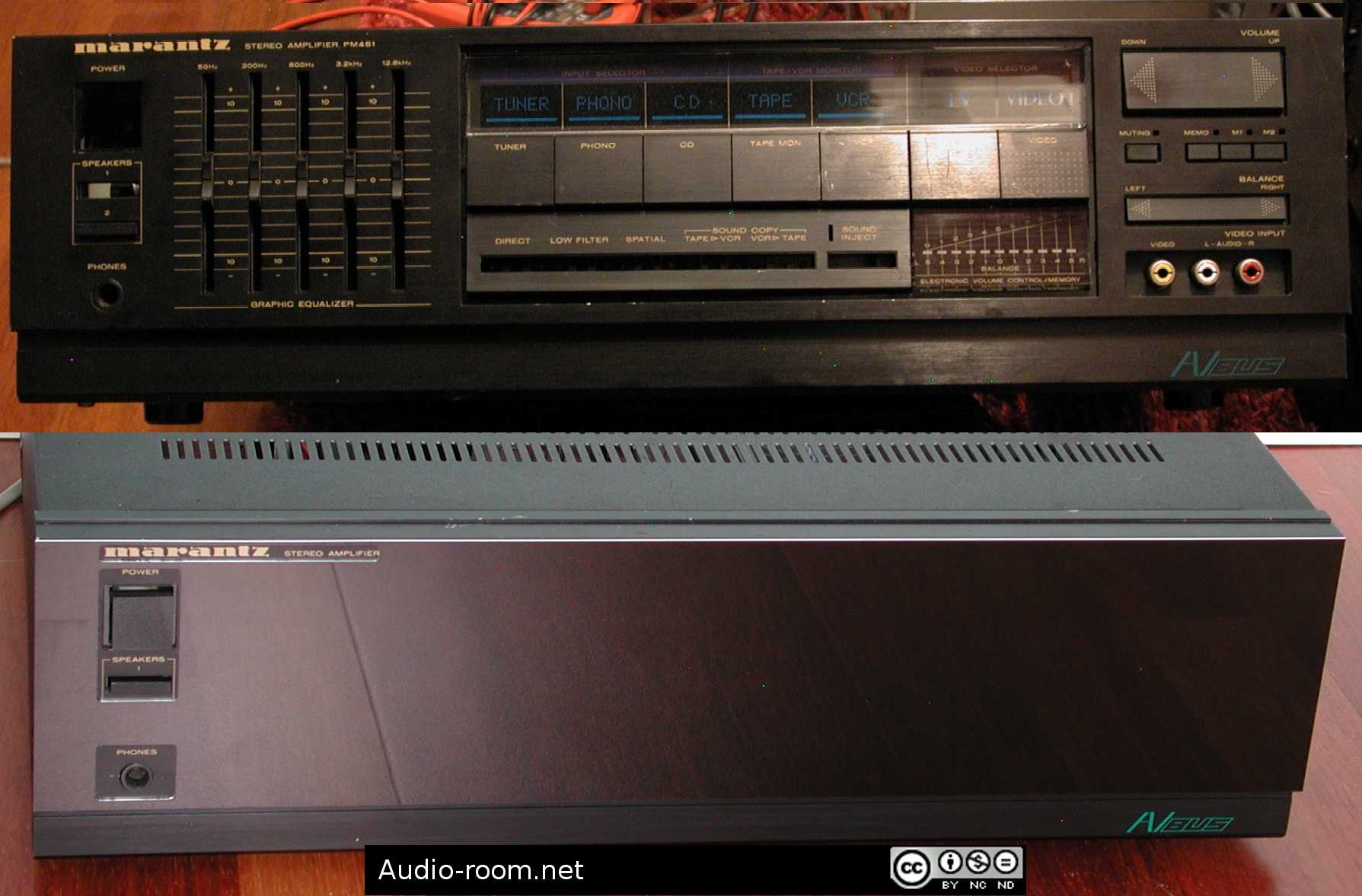
I started with designing a new face. I considered a number of materials: wood, black acrylic glass, black glass, aluminum, steel. I liked the idea of using glass, but it would be the most expensive and difficult option. After talking to few businesses that work with plastics and metal I settled on aluminum. I designed the plate that would cover the existing front panel, with openings for Marantz logo, power switch and one of the speakers switches, and the headphone socket.
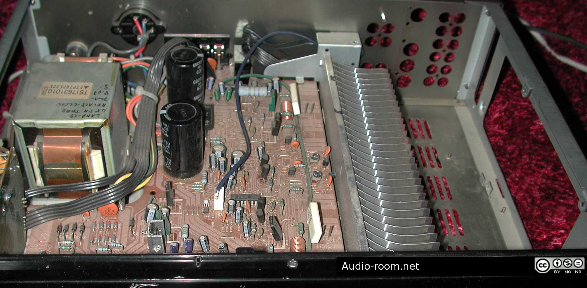
I removed all unnecessary PCBs (preamp, volume control, EQ, input selector, phono stage), input sockets from the rear panel, buttons from the front panel, etc. The only things that remained were the transformer, main PCB with PS and main amp circuits, the heatsink, the power switch, speakers switch, headphone socket, speakers socket, one set of inputs and the chassis ground screw. Of course I will harvest useful parts from the remaining boards (lamps, LEDs, capacitors, potentiometers, switches etc).
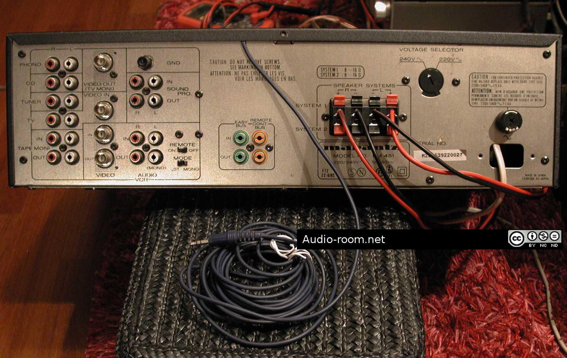
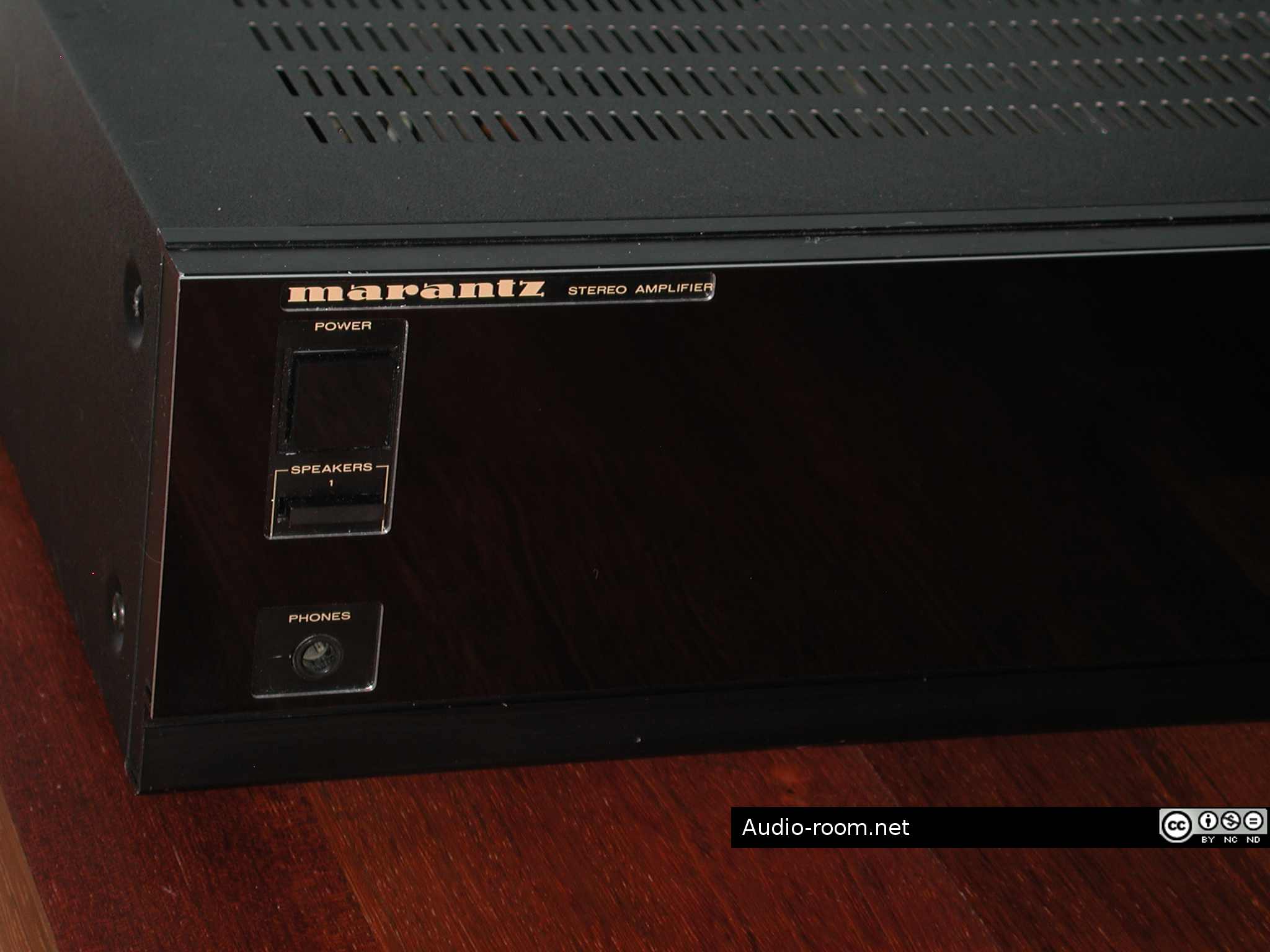
I decided to leave the original speaker connectors in place, because they are soldered directly to the main PCB (my original idea was to replace them with connectors for one pair of speakers). I set the Speakers 2 switch in OFF position and removed the button (I used it to replace the missing Speakers 1 button). This switch would be hidden under the new front panel and the Speakers 2 sockets inactive. This amp is no good with 2 pairs of speakers anyway.
I cut a part of the board with the set of 4 RCA inputs, fitted them in the openings in the center of the rear panel and wired two of them to the amp input on the main PCB, the other two are not connected to anything. 2 would be better than 4, but the set of 4 was more convenient for fitting.
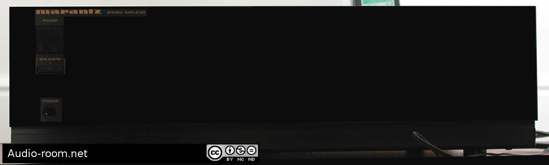
I fitted a new button for the power switch (my tech had lost the original button). The square black button is cut to size from 3 mm acrylic glass, glued to the holder I’ve made from pencil eraser with a hole drilled for mounting on the switch. I wrapped some red insulation tape around the holder to strengthen it, erasers tend to break under pressure.
Stage 2 completed. All the redundant parts have been stripped, proper RCA inputs connected, the unnecessary buttons have been removed and the buttons for remaining switches are in place.

STAGE 3
I picked up the new face ordered from an engraver. It’s made of 0.8 mm aluminum sheet, black glossy front. The cost was 30 euros, and it’s the only cost so far.
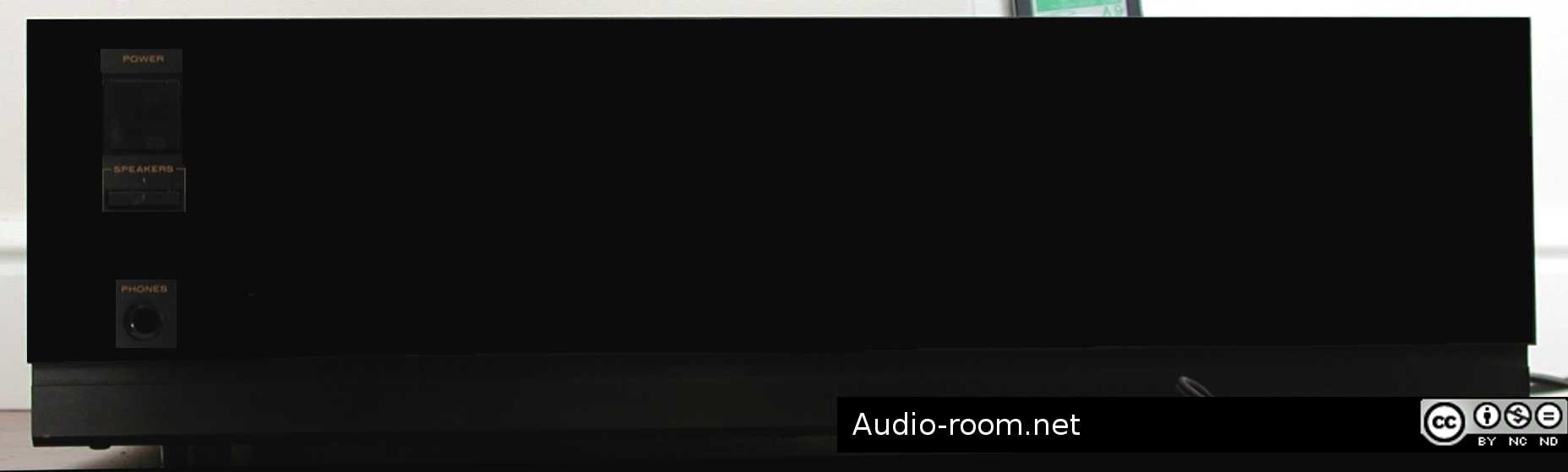
I attached new face on top of the original front panel using multiple small strips of strong, thin 2-sided adhesive tape. All the extruding parts of the original face had been removed, except the two buttons fitting in the opening cut in the new front panel (power switch and speakers switch). The other two openings had been cut for the Marantz name and the headphone jack.
The reason for leaving the speakers switch in place is that the headphone socket does not disconnect speakers, and leaving the switch in place was easier and cheaper than replacing the headphone socket with one that has switching function. I considered a smaller round opening for the headphone socket but I wanted to have some margin just in case, so I went with rectangular that matches the width of the upper opening for power and speaker switch.
Stage 3 completed. The new front panel is a perfect fit, now the amp looks classy and clean, like a power amplifier should.
One more thing remaining to do is the AC connector. Originally this amplifier had that wretched Marantz 2-pin AC socket you can’t find cables for. I removed it and attached a lamp cord for now. I will either install an IEC socket or replace the power cord with something a bit better (like a PC power cord) and cover the opening.
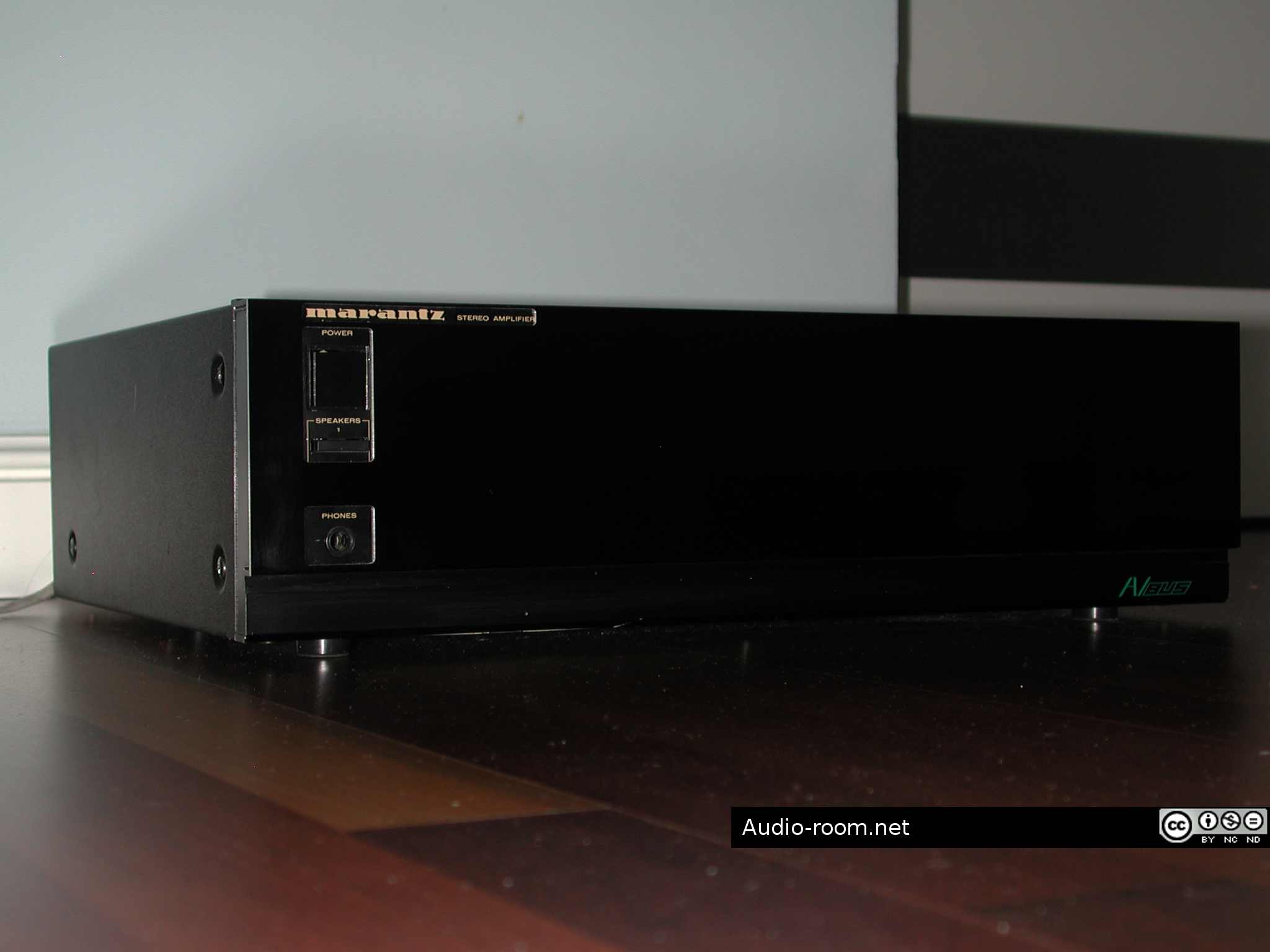
Covering the holes remaining in the rear panel after removing the RCA inputs is optional. I have a plate ready, but I might just as well leave the holes for better ventilation. I might try to remove or paint over the green “AV BUS” lettering (front, bottom strip), although it does not bother me much.
So, at the cost of 30 euros (new front panel) and 3-4 hours of work (tapping to the power amplifier section and testing, removing redundant parts, designing the new front panel and finding an engraver to make it, connecting inputs, making a new button for the power switch, attaching the new front panel), instead of a faulty integrated amplifier I now have a 60 WPC Marantz power amplifier that works, sounds good, and has a classy, shiny black face!
Specification (based on Marantz PM 451 technical information):
Continuous power (DIN): 2x80W / 4 ohms, 2x70W / 8 ohms
Continuous power (RMS): 2x60W / 4 ohms, 2x60W / 8 ohms
THD at RMS / 8 ohms: 0.05%
IM distortion: 0.05%
Damping factor 8 ohms: 35
Frequency response: 10 Hz – 25 kHz
S/N (Signal to noise ratio): > 93 dB
Dimensions: 420 x 118 x 330 mm
Weight: 8 kg
This is exactly what I want to do with a Pioneer VSX-AX10, thanks for the post, excellent job you did, very pro.
That Pioneer is a big one! I have an Onkyo HTR with a dead sound processor chip that will probably also end up as a power amp if I manage to locate the audio signal entry points to the main amp.
Hello, I love reading your blog. It is really very impressive. I want to leave a comment in your support. Carry on with good continuation. Best of luck for your blogging efforts.