Is it possible to use two amplifiers or receivers with just one set of speakers? This question gets asked a lot. There’s a numbers of reasons for trying to do that. You could have a home theater receiver for movies and a dedicated stereo amp for music (like I do) and not enough space to accommodate two separate sets of speakers for each amp (or a wife, who vetoes this solution). You could have one big, powerful “performance” amp for active or loud listening, and another, smaller amp that draws much less power for background music and nighttime listening, when the family’s asleep and loud music is a no-no (like I do in another room). Or you simply want to quickly compare 2 amps (like we do very often here at AR), A/B test them without having to make long pauses for switching the amps off, disconnecting speaker wires from one amp and connecting them to the other amp.
So, again, is it safe to connect two amps to one set of speakers? If you do that directly, simply run speaker cables from both amps to your speakers – definitely not. If you do that, and then turn on both amps, you will fry at least one of them, possibly both. Even if you think you’ll be extra careful and always remember to switch off one amp before switching on the other, and you actually are that careful, sooner or later someone else will try to listen to some music using your gear – and poof goes your nice amp. This exact thing happened to a friend of mine. He was careful, but his daughter wasn’t.
Is it possible to use a speakers selector switch in reverse for this? Well, not really. There are three problems with the majority of speaker switching boxes. One is that they usually have common ground. You do not want to have common ground between two amps, this could negatively affect their performance (and sound quality) and in some cases also case damage – there are amps that have fully balanced outputs and cannot have common ground between speaker connectors, for example some Class D amps. Another problem is that many speaker switches have protection and/or impedance matching circuits, and those could also affect sound quality, so you do not want that. But most importantly, most (actually almost all) of these switches allow to select more than one set of speakers at the same time – which becomes selecting more than one input amp when you use the switch in reverse. And if you do that, it’s exactly like directly connecting two amps to one set of speakers – if both amps are on, at least one of them will get fried.
But we’re on the right track now: what you need is indeed a switch – but it has to be a specific type of speaker level switch in order to accommodate 2 amps. Here’s what it needs to do:
1. It needs to be a “break before make” type (break connection to one amp before making a connection to the other amp) to prevent both amps from being connected to each other even for a split second – it should make it absolutely impossible to select both amps at the same time.
2. It needs to switch all 4 connections: L+, L-, R+, R- separately (no common ground).
3. Ideally it should not have anything else inside except binding posts, wires and the switch itself (no resistors, no protection circuits, impedance matching etc.).
With a switch that meets all the above conditions, you can safely connect two amplifiers (or two receivers, or an amp and a receiver) to one set of speakers. They can be on at the same time and you can switch between amps without having to turn them off.
There is one exception: for many tube amps it is very unhealthy to be on with no load (no speakers connected), so If you have a tube amp, better get another set of speakers.
The only commercially available switch I know that does all that is Beresford TC-7220. Unfortunately that switch is quite expensive – it costs $120, which is a lot for a box with a few binding posts, passive switches and some wire. Still, it is pretty much the only thing you can buy that will do the trick safely, so if you want a ready-made solution, that’s what we can recommend. But if you don’t want to spend $120 on a switch, you can built one yourself. Which is exactly what we did here at AR.
BUILDING AN AMP/SPEAKER SWITCH
The simplest and cheapest option is to built a switch box using a 4PDT switch. We’ve built two, the total cost is around $10-30, depending how cheap you can get the switch and what type of binding posts and enclosure you use. Here’s how we built one of them. It’s the more expensive one because of banana plug-ready connectors; if you use spring-type connectors, it becomes very cheap.
You will need the following parts:
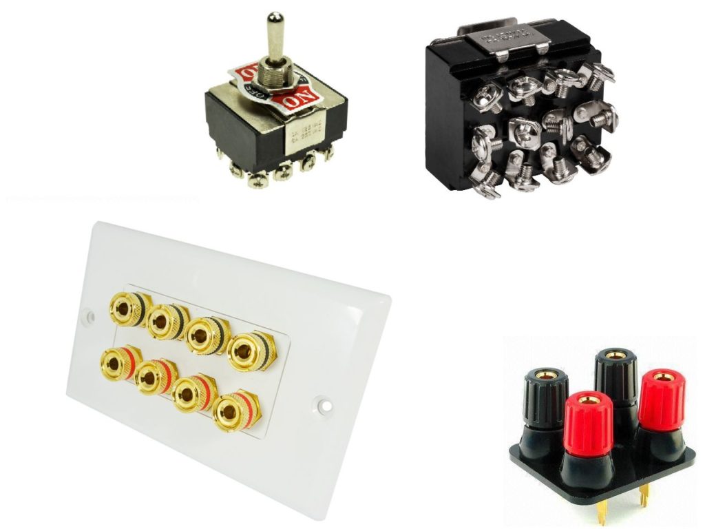
1. One 4PDT switch or two DPDT switches (we recommend toggle switches)
2. 3 sets of stereo speaker binding posts
3. 1-1.5 m of speaker wire to connect binding posts to the switch (6 short sections)
4. An enclosure
5. Mounting screws and/or glue
Depending on the type of switch and binding posts, you might need solder wire and a soldering iron to connect internal wiring. Also, depending on the enclosure you use, you might need tools to make walls, drill holes etc.
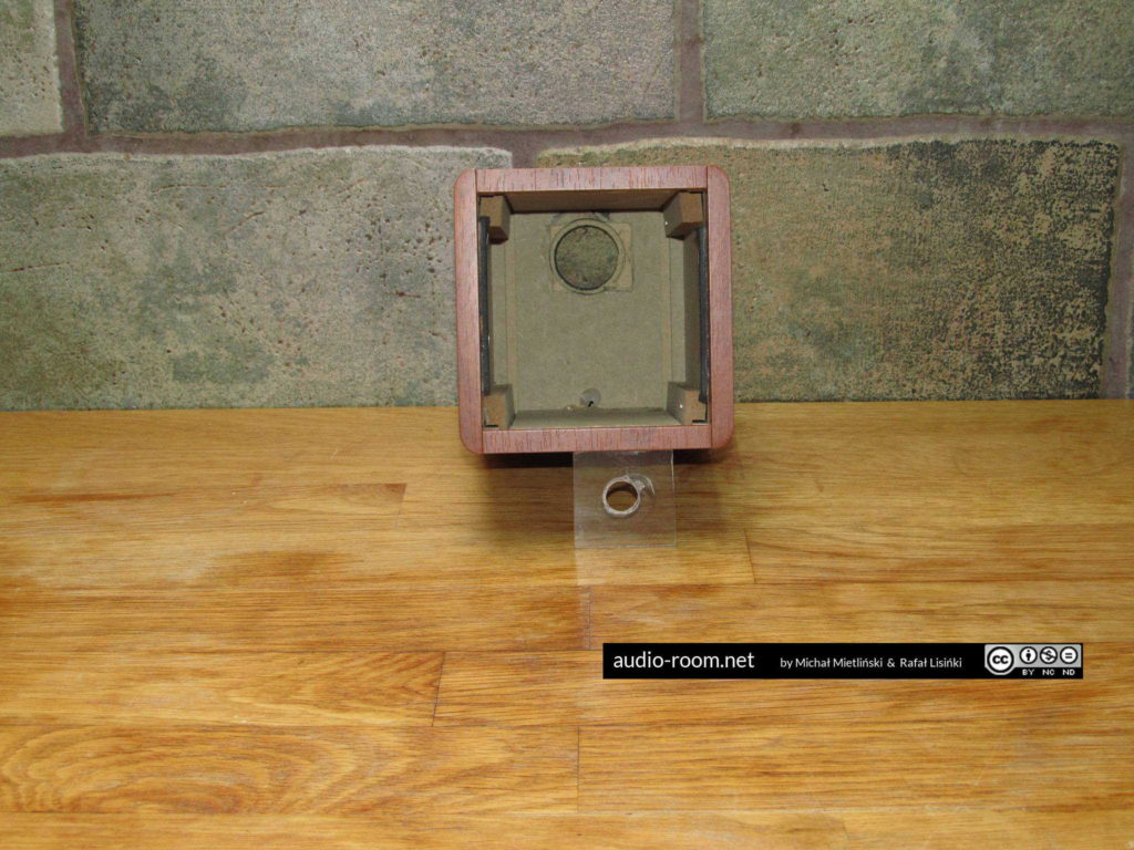
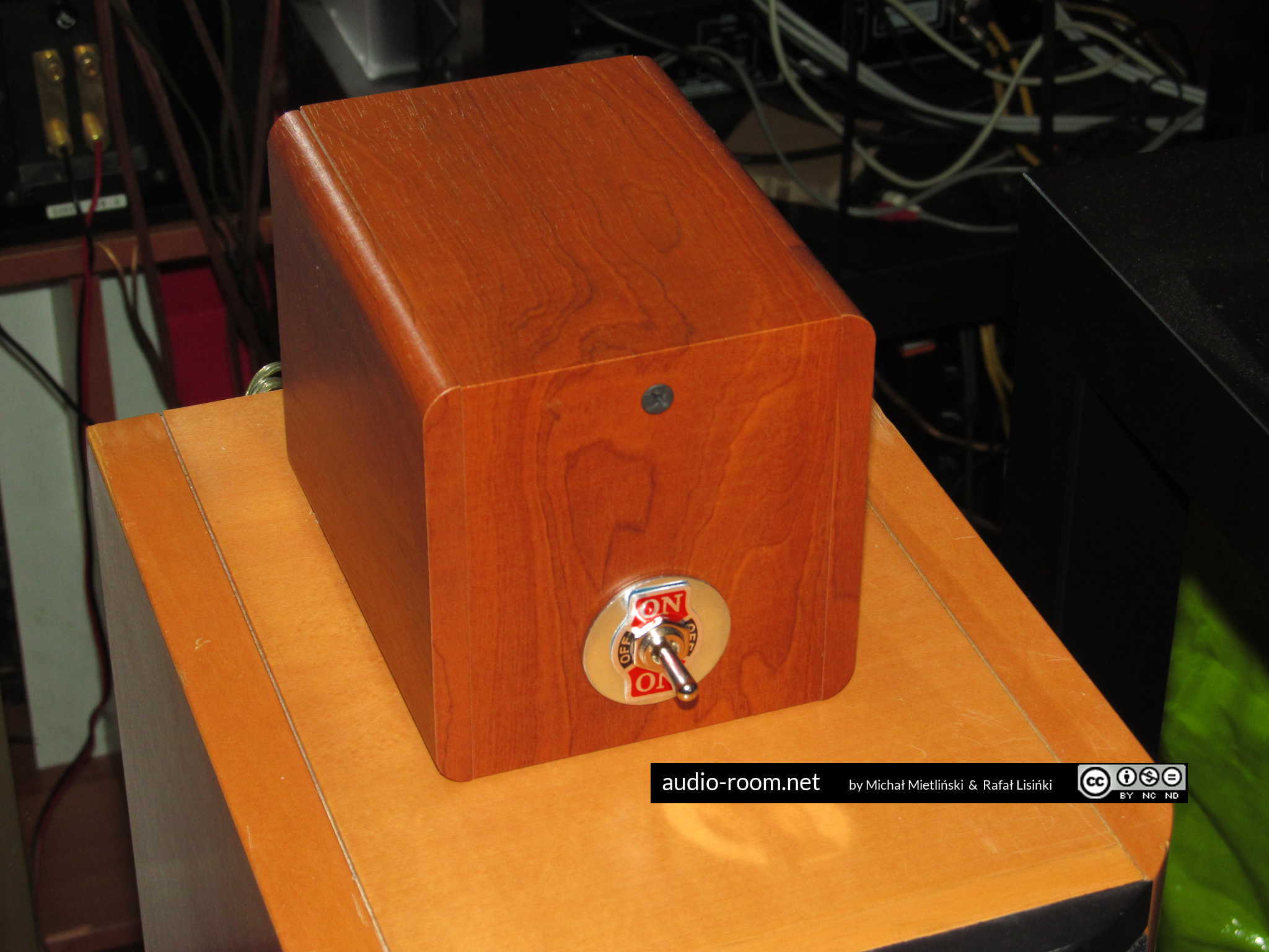
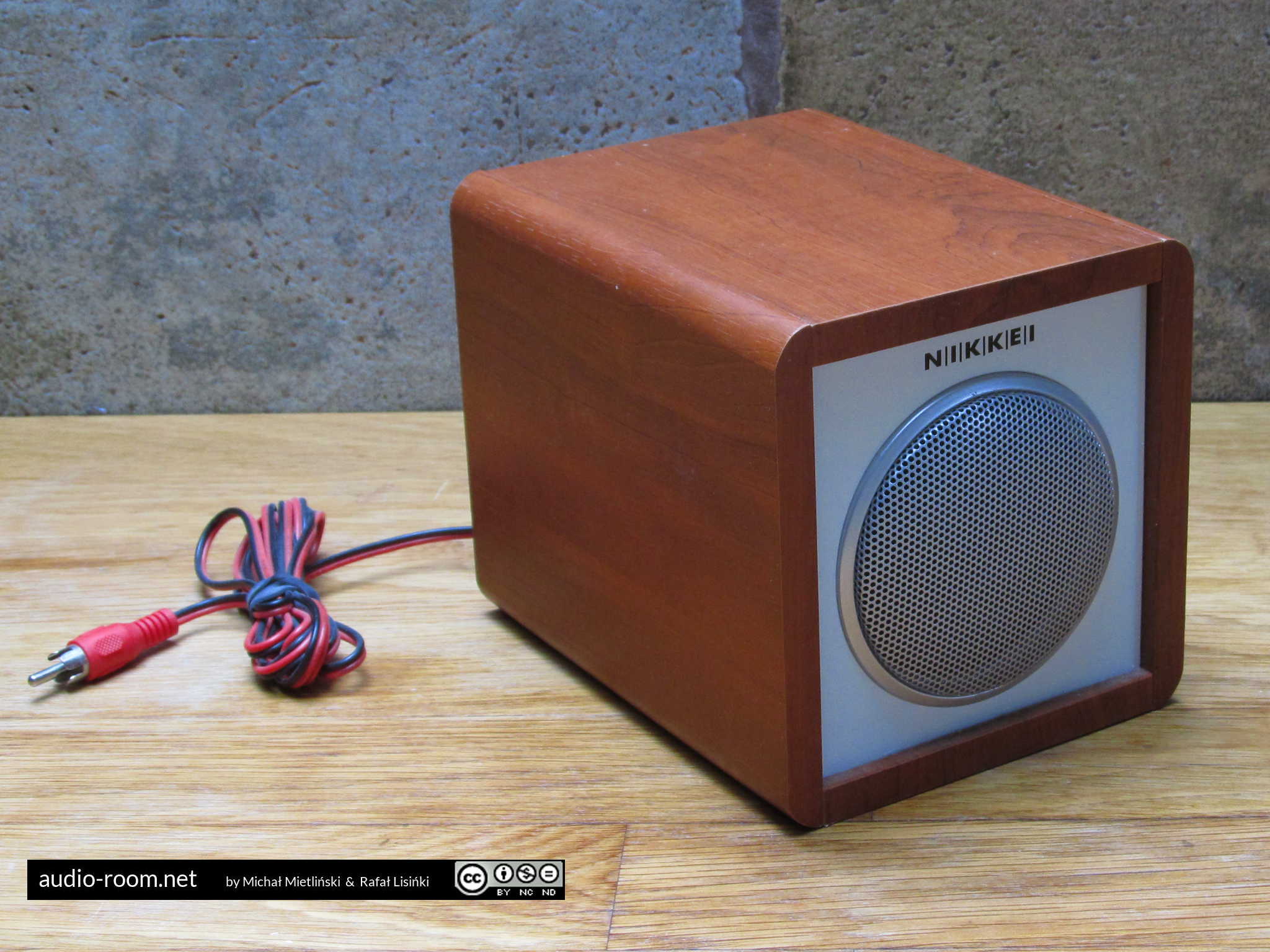
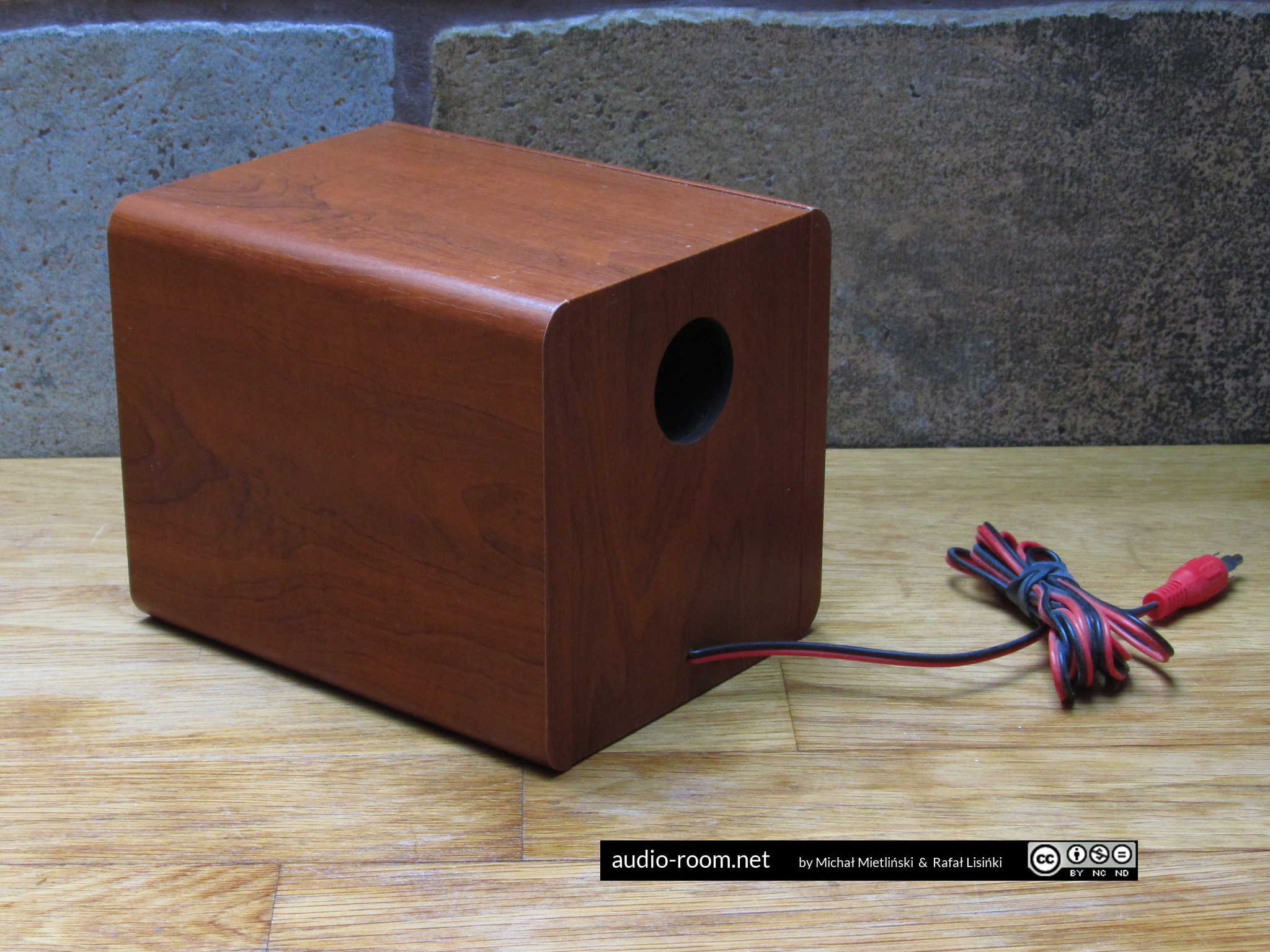
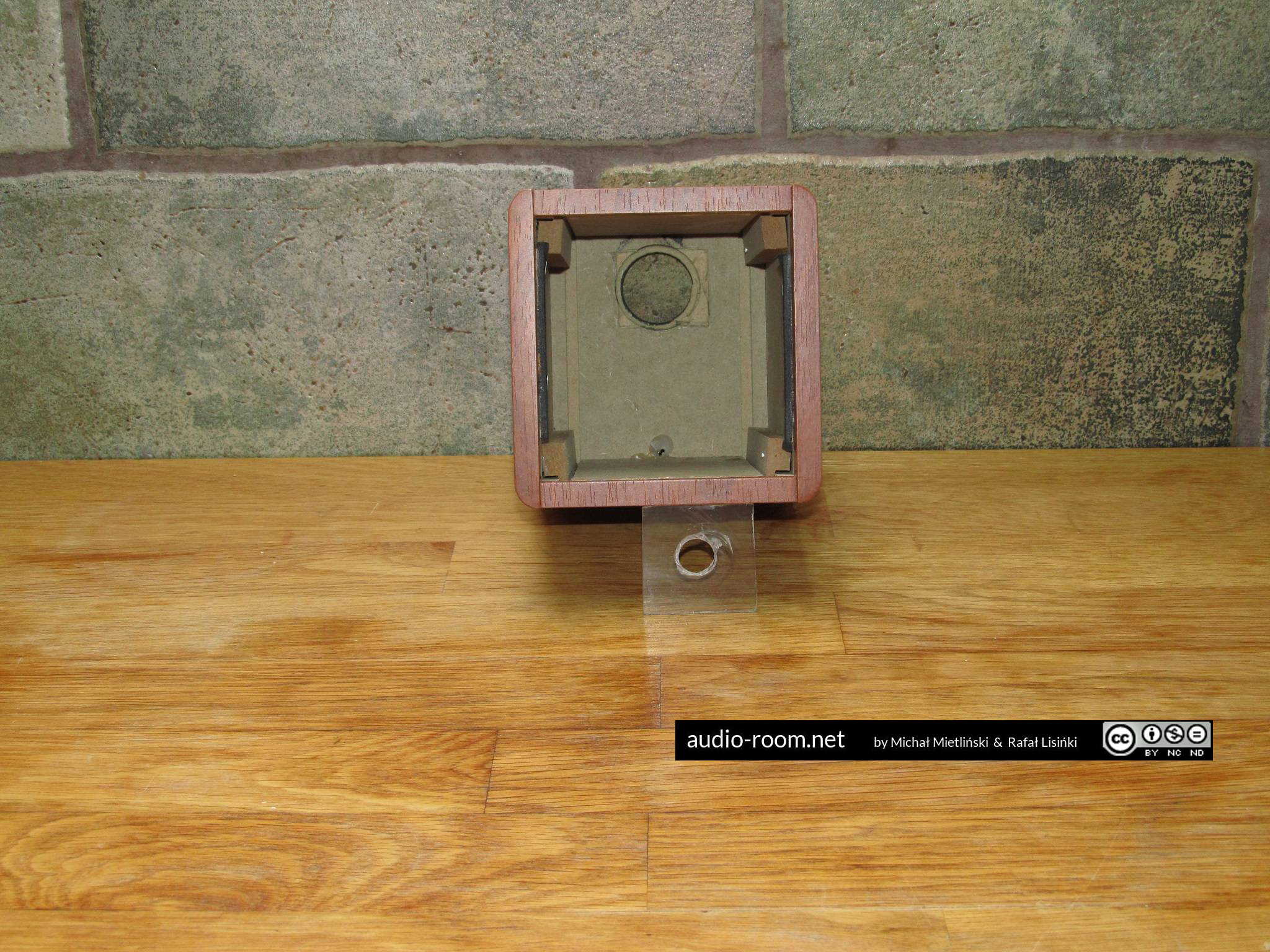
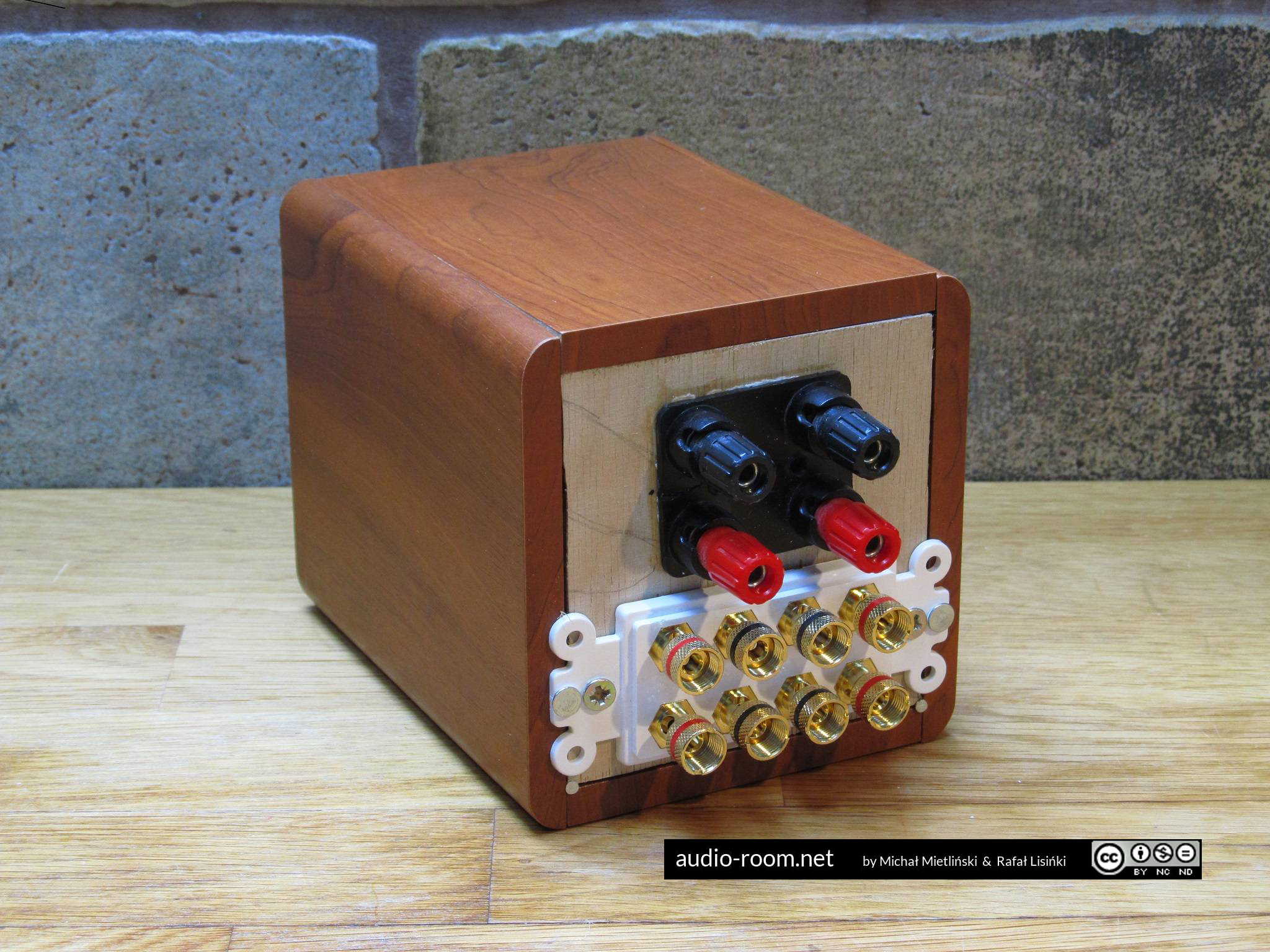
We used an enclosure of a nice-looking but crappy speaker as a housing for our switch.
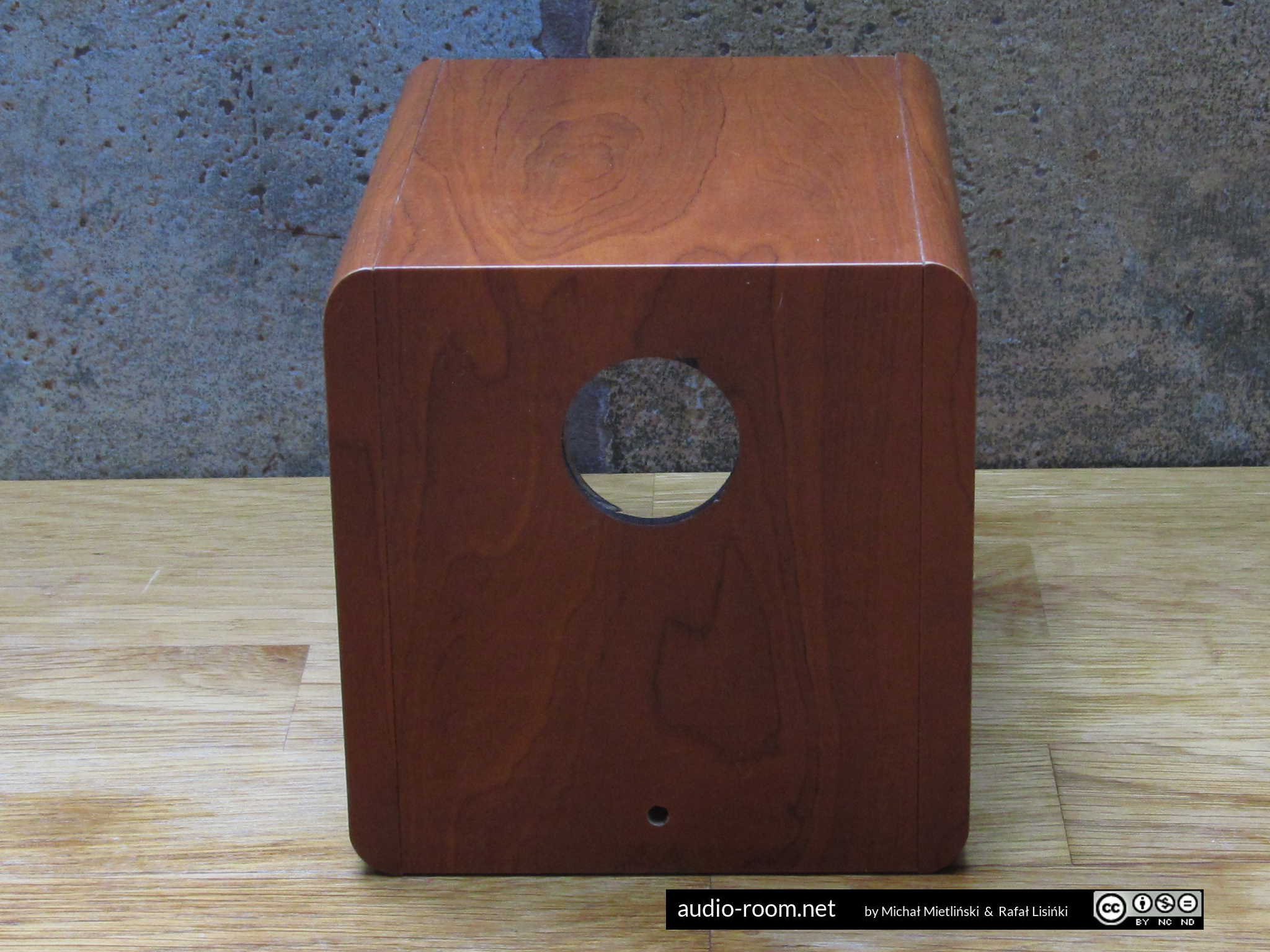
We removed the driver and the front wall, and the bass tunnel from the back. As a result, we had a nice box without one wall and with a round opening in the opposite wall.
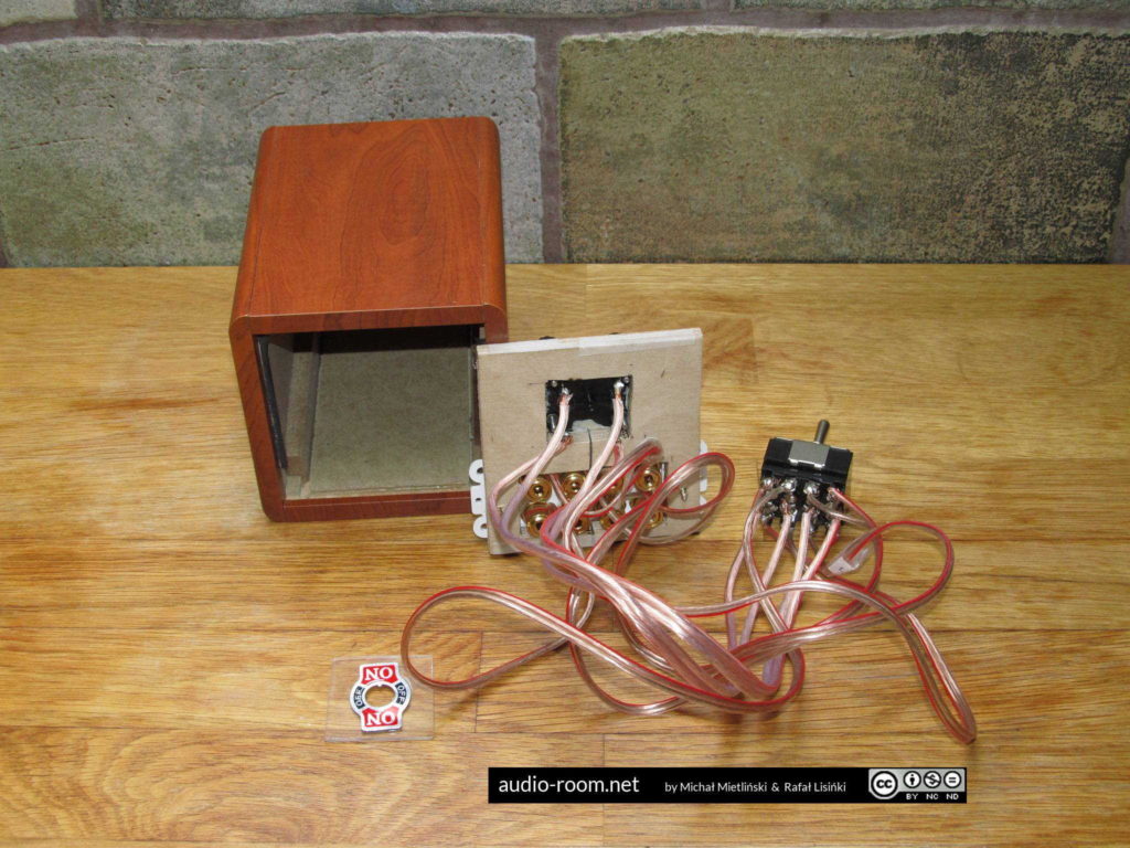
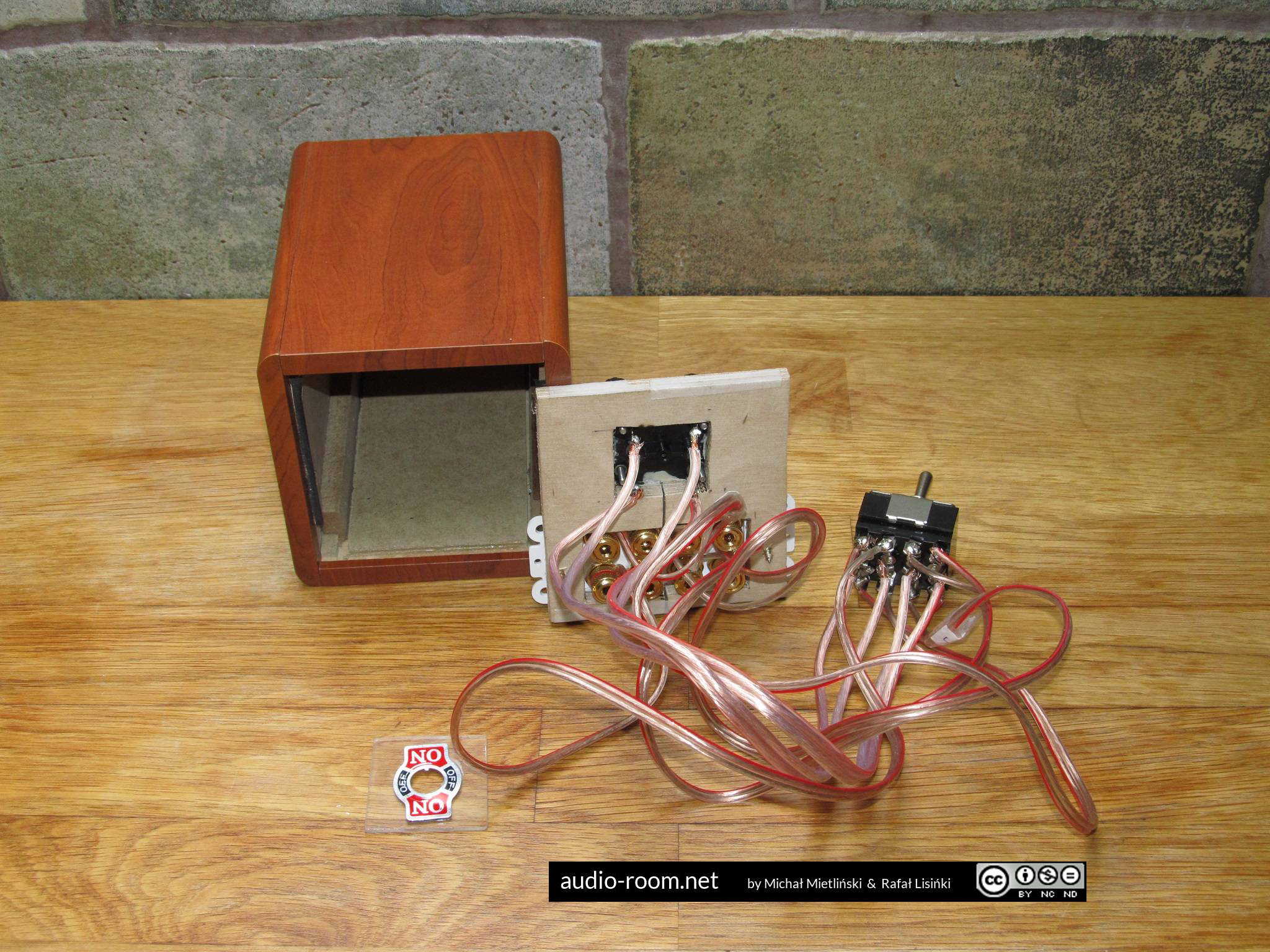
We cut the missing wall from plywood and made holes for binding posts. We used speaker wire to connect the binding posts to the switch.
A 4PDT switch has 12 connectors, usually 4 connectors in 3 rows. In this application, the two outer rows are for amps. The row in the middle is for speakers. Like this:
| A1 L+ | A1 L- | A1 R- | A1 R+ |
| SP L+ | SP L- | SP R- | SP R+ |
| A2 L+ | A2 L- | A2 R- | A2 R+ |
A very important thing when connecting wires to the switch and binding posts: make sure that each wire is tightly secured with a screw or well soldered and there are no loose strands that could cause a short. If you solder the wires to connectors it’s best to isolate them with heatshrink after soldering. Test all connections after soldering for conductivity and possible short circuits between connectors. If you short connectors you will fry your amp, so be extra careful.
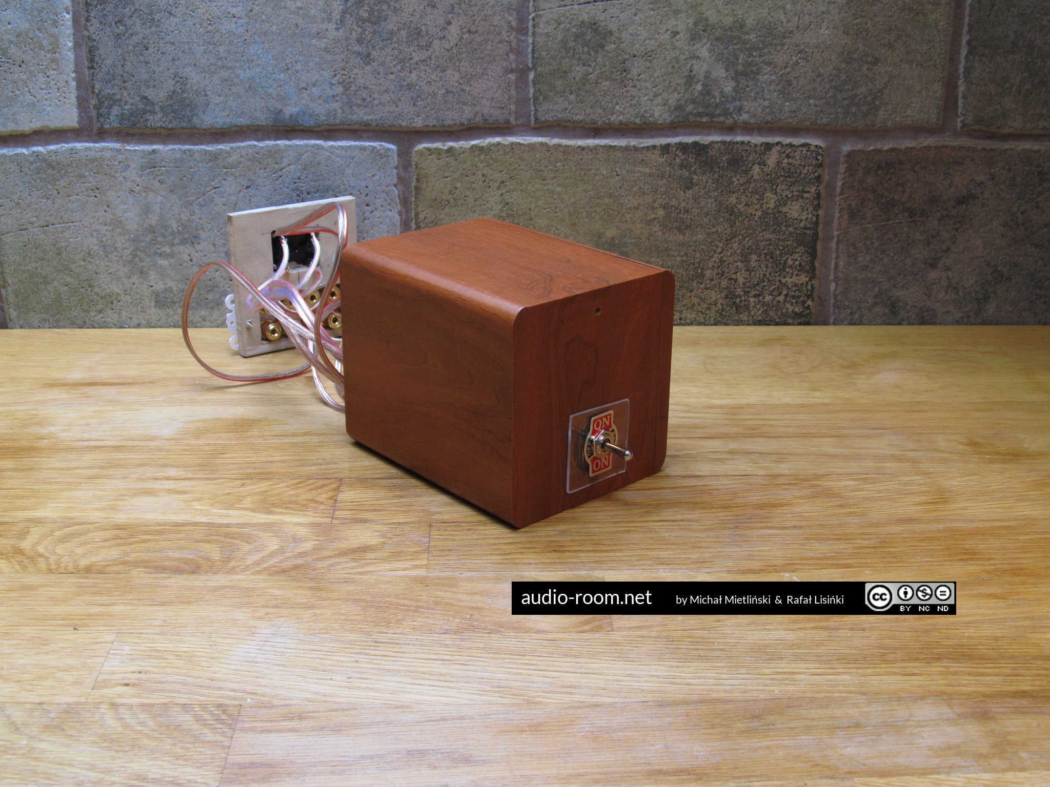
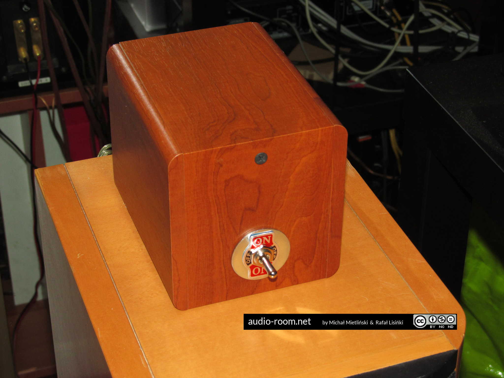
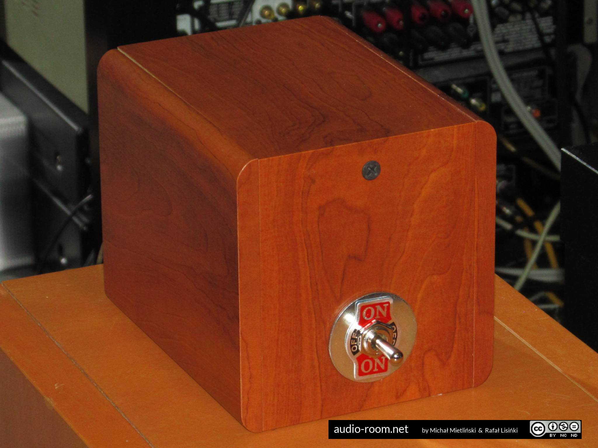
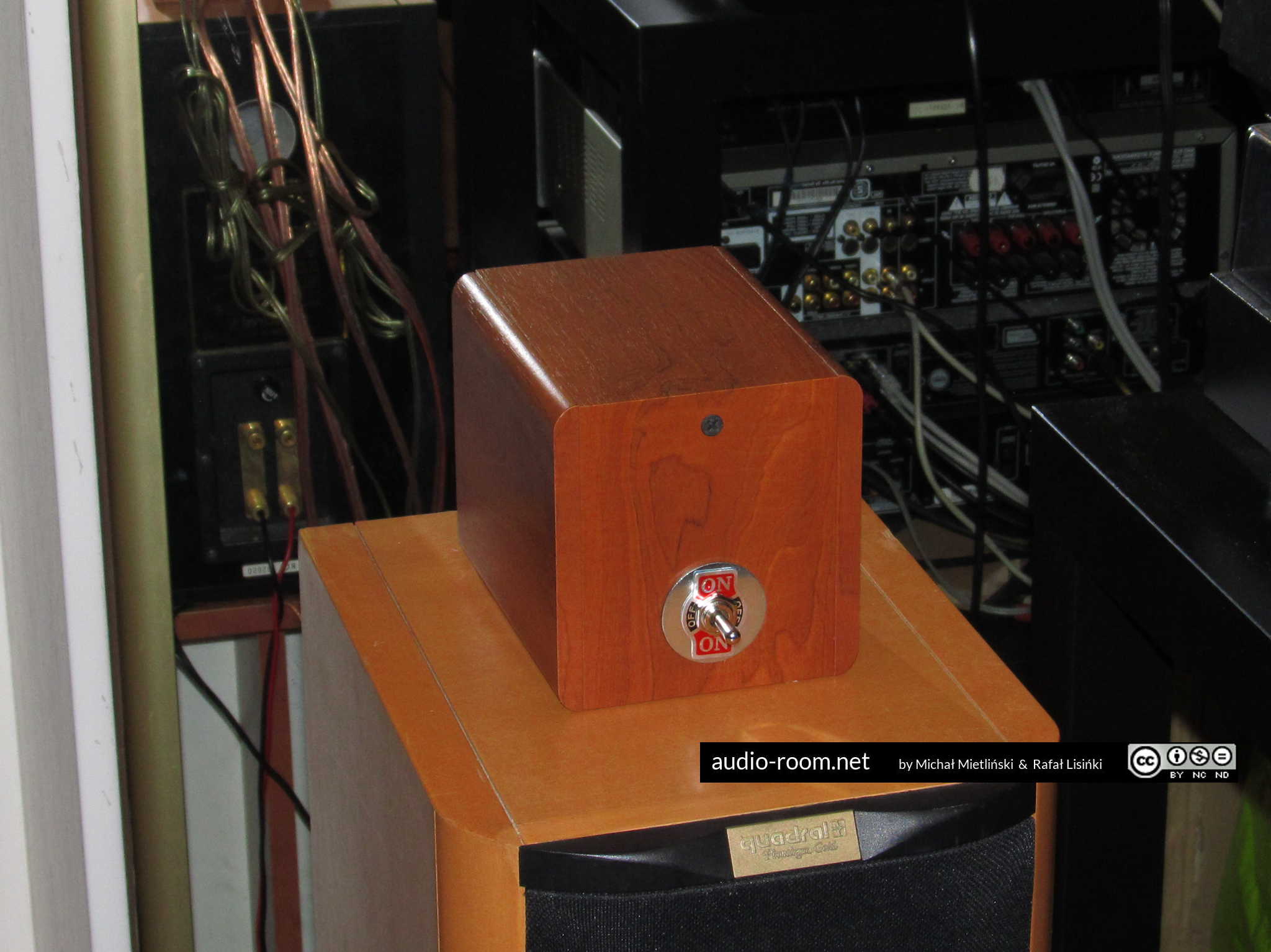
We installed the switch in the opening left after removing the bass tunnel.
Then we fitted the rear wall with binding posts.
Wires sometimes get loose during assembly, so at this point all connections of the switch should be carefully tested again for short circuits. Make sure you do that before connecting amps.
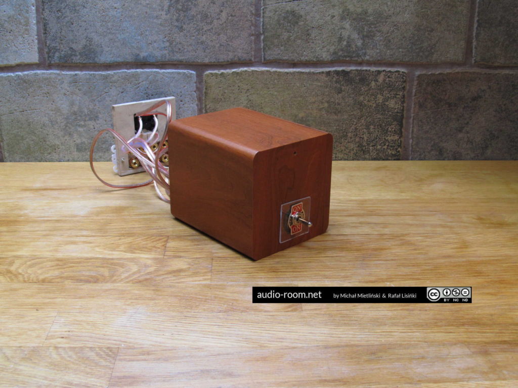
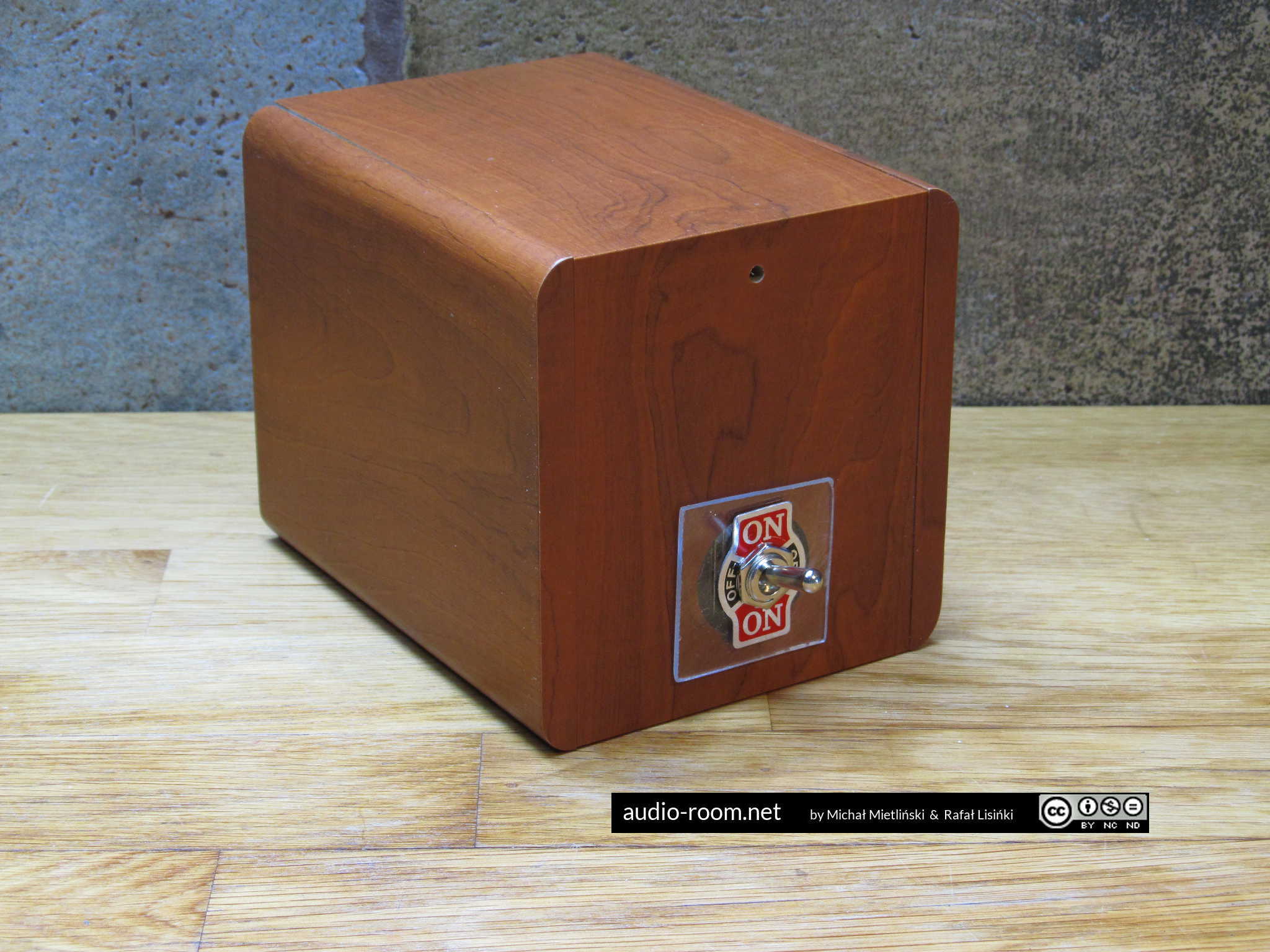
That’s it all done. This switching box works for either two amps connected to one set of speakers, or two speaker sets connected to one amp. You can select only one position at the same time. If you want a switch that will accommodate two amps and two sets of speakers (exactly like the $120 Beresford does), you will need one more 4PDT switch and one more set of stereo speakers binding posts. In that scenario, the connections from the amp binding posts to the outer rows of the first switch remain the same; the first switch’s connectors marked SP XX in the above table (the middle row) are connected to the corresponding connectors in the second switch, and the outer rows of the second switch are connected to speakers binding posts for two sets of speakers. The first switch switches between amps, the second switch switches between two speaker sets.
The whole process (including making the enclosure) took us about two hours. The result is a functional, safe, and aesthetic switch that allows to safely connect two amps to one set of speakers and switch between them even when the amps are on, just like the $120 Beresford switch, but ours costs only $22 in parts (again including the cost of speakers that we gutted to make the enclosure). The most expensive part was the speaker wire binding posts – the white ones cost $12. We used them only because they were already sitting in our drawer. There are much cheaper alternatives (both spring-type and banana plug ready) and if you use those, the total cost will be closer to $10.
EDIT (25.05.2019):
After 2 years of very heavy use, our switchbox broke. The 4PDT switch itself stopped working, contacts inside got loose or broke. It did not make short, just stopped making a connection.
Our switch was really abused, we do a lot of A/B tests, during which we do 20-50 quick flips in one hour (in addition to using the switch normally every day). We expect that with normal use (1-2 flips per day), such a switch should work properly for at least 5 years. But if you notice that it starts getting loose when you flip it, or doesn’t always make a good connection, it’s best to replace the 4PDT switch at once.






Hello Rafal,
I would like to create a selector-switch box for 3 amplifiers to my set of speakers.
I’m using the speaker outputs A and B on every amplifier.
The set of speakers includes : 2 columns (high-medium), 2 bookshelf speakers (med-low) and one subwoofer.
Using the same principle that you’ve described for 2 amplifiers and 1 pair of speakers,
– do you think this would be safe,
– would you recommend it,
– what would be the schema to make it.
Very best regards.
François
Hello François,
Adding switches in the signal path can always degrade the sound a bit. But with switches of this type any change in sound should be minor or even inaudible. My way of switching is safe for both amps and speakers, so it can be used also in your scenario.
To accommodate 3 amps and 2 pairs of speakers you can daisy-chain 3 switches made according to the same principle as my switch. Or actually 2 switches like mine to switch between the amps and one cheap, ready-made speaker selector, because switching between speakers is a less sensitive issue and you can have both pairs of speakers playing at the same time and, unlike amps, they can have common ground. Unless one of your amps does not tolerate that, in that case it is better to use my (safer) switch.
So we have:
Amp A, Amp B and Amp C
Speakers A and Speakers B
Switch 1, switch 2, switch 3
Remember that my switches can work both ways, this means that they can have either 2 inputs and 1 output or 1 input and 2 outputs.
Connection would go like this:
1. Switch 1: 2 inputs, 1 output. Amp A and Amp B are connected to the inputs of switch 1. It selects between Amp A and Amp B.
2. Switch 2: 2 inputs, 1 output. Amp C and the output of switch 1 are connected to the inputs of switch 2. It selects between Amp C and whichever amp has been selected with switch 1 (Amp A or Amp B).
3. Switch 3: 1 input, 2 outputs (this one can be ready made if all your amps can handle common ground and more than one set of speakers connected at the same time). The output of switch 2 is connected to the input of switch 3. The outputs of switch 3 are connected to Speakers A and Speakers B.
With the above system, switches 1 and to select amp A, B or C (only one at the time). Switches 1 and 2 MUST be like the one I used in my project. Switch 3 selects speakers A and/or B. This one can allow to select both speakers and have common ground if ALL your amps can handle that. If any of your amps can’t handle that, use the safe switch (like mine).
That covers amps and stereo speakers. To accommodate subwoofer I would have to know what kind of subwoofer you’re using and how it is connected to each of your amps. If it’s a passive or active “pass through” subwoofer that you connect to the speaker outputs of an amp, and then connect stereo speakers to the subwoofer – you can connect it the same way to one set of outputs of switch 3. If it has a different connection method, I’d have to know the details.
Hope that helps,
Rafal Lisinski
Great info, but I’ve got an even more complicated setup. I have 4 different 5.1 home theatre amps in my garage. At the moment, only one is connected. I have 3 sets of speakers connected plus a powered subwoofer. These amps were all thrift store purchases but were all pretty good quality, Denon, Onkyo, Marantz, etc… ranging from 250 watts to 400 watts each. The speakers are one in each corner, and 2 halfway down the wall, and the subs are in the center. They are spaced around the room alternating left and right speakers, so no matter where you stand in the room you hear the music in stereo. I want to be able to switch between amps just to see which one sounds best. Am I going to need 4-way switches or what?
That is a lot of amps and speakers. To my knowledge, there are no reasonably priced mechanical switches that would allow to switch between two 6 channel amps, and you have four. You would need 12PDT switches, which do exist but are very expensive.
I can think of 2 solutions.
1. The complicated way: you build several switches and maybe coupling bars for levers that would allow to flip 3 switches in one move. 3 switches like mine used together allow to switch between all channels of two 6 channel amps (switch 1 for front channels, switch 2 for rear channels, switch 3 for center and sub). Then, you can daisy-chain switches: you connect an additional switch to each of the inputs of the switch that is connected directly to speakers. If my calculations are correct, with a total of 9 switches like mine you can compare four 6 channel amps. That is a lot of switching and a lot of switches to build, wire etc. I would probably choose death.
2. The easy way: you build one switch like mine and compare front channels only (stereo mode). If front channels sound good, chances are the rest is at least acceptable. If front channels sound bad, the amp will not sound good in 5.1 mode either. By comparing two amps at a time, you can quite quickly figure out which amp sounds best.
Excellent solution!
I have a slightly different question and want to be certain I have it right.
2 receivers/amps, 2 pairs of speakers Utilizing Channels A & B.
The first receiver is Surround-Using Channels A & B, + Klipsch Subwoofer.
The second receiver, Marantz 2252, Using Channels A & B (same speakers), but no subwoofer.
Thank you so much for the knowledge you’ve already imparted.
Stephen
Hi Stephen,
Glad my article is helpful!
Now to your specific situation. I understand that the subwoofer is not important because you only use it with the surround receiver and you only need to connect speakers A and B to two receivers. There are two possible scenarios:
1. You use either speakers A or speakers B (but never both at the same time) with each receiver
2. You use both speakers A and speakers B at the same time with each receiver
I understand that your situation is the second scenario.
Also, one of your amps is a stereo receiver (the same signal goes to speakers A and B) and the other amp is a surround receiver (different signal goes to speakers A, different to speakers B). That is also important. That means that even if you ALWAYS use both speakers A and B, they cannot be connected to the switch in parallel, because only the stereo receiver uses a parallel connection. The surround receivers actually works as two separate amps (front speakers amp and rear speakers amp). I understand that in the case of the surround receiver speakers are connected to front and rear outputs, and not to front A and front B outputs (that would be a very different connection and actually similar to using a regular stereo amp).
In that case, the best solution is to use two switchers like the one I described. One switch switches speakers A, the other switches speakers B. Unfortunately there are no simple, sturdy and cheap mechanical toggle switches (that I can find) that would allow to switch a total of 8 separate signal lines (and that’s how many you get with 4 speakers), which is why you need a separate switch for each pair of speakers. It’s not a big problem, you just flip 2 switches instead of one. But it does mean two times the work, materials and time needed to build the switcher.
The two switches and corresponding speaker binding posts can be fitted into one enclosure, obviously it would need to be larger.
This solution (2 separate switches for speakers A and speakers B) will work perfectly fine in other scenarios, for example with 2 stereo amps that use speakers A and B, or with a stereo amp and a surround receiver where the speakers are connected to front A and front B outputs of the surround receiver (as opposed to its front and rear speaker outputs). But in some cases a simpler solution would suffice.
Hope that helps. Let me know if you have any more questions and good luck!
Rafal Lisinski
Thanks for this post
Managed to put a switchbox together this afternoon and It works a treat, no more ‘protect’ mode.
Total cost here in Aus, including enclosure was around $17.
Very happy with the result.
Hi Eric,
Glad my post could help. I’m curious to see your switchbox, send me a photo if you can. My email is in the ‘Contact Us’ tab.
So do I understand correctly that you were using a different switchbox before and it was sending your amp into protect mode? What sort of switchbox was it?
Rafal Lisinski
I am currently building one of these and had a question. Could this used to use one turntable with two amps subbing RCA jacks? I see no reason why not do you?
Sure, but it’s overkill. You can also use a cheap ($2) AV switch for that purpose. Search for “AV RCA Switch Selector Box”. Common ground between channels is not a problem with turntables, and you can use the 3rd RCA socket to connect and switch the grounding wire.
AV RCA Switch Selectors can have resistors inside, which degrade signal quality.
I disassembled 2 cheap passive AV switchboxes that I happened to have at home and I did not find any resistors or other components inside that would alter the signal, just sockets, a PCB with tracks and a switch. The quality of components if as poor as can be expected, but there are no wires, so it should primarily affect the switch durability, not signal quality. At least it shouldn’t do any more harm than an average quality cable would.
I used one of these switches for a turntable in my decent (but not hi end) system without any problems or audible signal loss. I used the video socket to connect (and switch) turntable ground. But whether such a switch degrades the signal could vary depending on the quality of the audio system (there could be an audible difference with a hi end system – just like with better and worse quality cables).
Active switchboxes are a different story, in my experience they do degrade sound and have their own background noise.
Of course, toggle switches can also be used for this purpose. A 4PDT switch has the right number of connections (L+, R+, common ground, turntable ground). Common ground is not a problem with turntables in most cases. But i still think building a switchbox with a toggle switch is overkill for switching the source-amp line (including turntables), considering that a simple AV switchbox does the job and it’s very cheap. Unless it doesn’t work (or causes signal degradation) in your system.
BTW, resistors should not degrade signal quality (unless they’re poor quality themselves), they should simply make the signal weaker, quieter. That, of course, is not preferable in the case of signal from a turntable, which is very weak to begin with.
Hello,
I am trying to get parts for this idea but I wondered if I can just buy
a speaker switch and modify it?
https://www.kjell.com/se/sortiment/ljud-bild/hogtalare/tillbehor-for-hogtalare-aktiva-passiva/hogtalarswitch-1-till-2-p39123
If I open this unit and modify it following your instructions for a
single switch and remove the second switch this would be the cheapest
and most convenient solution for me. What do you think?
Appreciate any help. Thanks.
Adam
Hi Adam,
Buying the speaker switchbox you mention might be an option but:
– that speaker switchbox costs almost exactly the amount we paid for all parts (including the enclosure) of the switchbox in our article, since then we’ve built another switchbox that was 30% cheaper because we’ve found cheaper sockets; of course that depends on the cost of parts in your area but you would still have to buy some parts you will need to make the conversion: at least a 4PDT switch and probably some wires;
– you would still have a lot of work to do, you would have to replace the two switches that are there now with the switch we recommend (a 4PDT switch), and fitting a 4PDT switch in an opening left after one of those flat cradle switches might be difficult and it might turn out that you can’t fit a 4PDT switch with screws for wires (it’s quite large and might not fit in this enclosure) and have to use a smaller switch that you have to solder wires to – soldering 12 wires is more tedious;
– you will probably still have to rewire the speaker wire connectors: this switchbox probably has common ground (they usually do) which is OK if you switch between speakers, but should be avoided if you want to switch between amps;
– you would still end up with a switchbox that has poor quality wire connectors (these spring-type connectors in the back – we do not recommend them, they are a problem if you use a wire that’s too thick or too thin for them and they break more easily than even the cheapest screw-type connectors).
That’s the potential problems I can think of from the top of my head. In short: yes, converting that speaker switchbox should be doable, but it might not be easier or cheaper than building a switchbox from scratch. Buying parts could be cheaper depending on the prices in your area, conversion of that speaker switchbox might involve a bit less work or not, depending on its internal wiring and how easy or difficult fitting a 4PDT switch would be.
Hope this helps. Good luck on your project. If you have more questions, drop me an email, and let me know when you’re done, I’ll be curious to see a photo of you switchbox (whether you build it or convert the one you’ve linked).
Kind regards,
Rafal Lisinski
If wired in reverse, will any of this product accomplish the same as your build?
https://www.amazon.com/Stereo-Speaker-Selector-Switcher-Combiner/dp/B00CZNXKRA – I feel like this one might be the closest device to yours.
https://www.firefold.com/stereo-2switch?gclid=Cj0KCQjw9NbdBRCwARIsAPLsnFZsZw8vn3YmlP2yhEH3RpnuOZEPaccx-JE-zKMrF6DJHOwPyEoXKu4aAipXEALw_wcB
https://www.amazon.com/Stereo-Speaker-Selector-Switcher-Combiner/dp/B0184M4TVQ
https://www.amazon.com/Switch-Stereo-Receiver-Speaker-Selector/dp/B00YNUICRQ/ref=sr_1_fkmr1_2?s=electronics&ie=UTF8&qid=1538688845&sr=1-2-fkmr1&keywords=ab+stereo+speaker+selector
This one seems a bit different https://www.monoprice.com/product?p_id=8231&gclid=Cj0KCQjw9NbdBRCwARIsAPLsnFY3irQDDTwoTY2nCMGMrJqjC3JZGhr5XVCGtgZnLWA7odr7z3nH4ecaAkCBEALw_wcB
If any of the above would work, could you please let me know advantages/disadvantages vs. yours and Beresford TC-7220? I really appreciate your insight. A tube amp just arrived and I’m looking forward to hooking it all up.
I’m afraid the first 4 options would not work One reason is that it’s quite likely they all have common ground. It’s not certain, but it’s simply much easier and cheaper to build a selector with common ground and it is not a problem if it is is a speaker selector. But can be a problem if it is an amp selector. More importantly, they have the A+B selection possibility, which is what you select if you want to fry your amps (it would connect amps to each other and fry output transistors).
The fifth option (Monoprice) is theoretically designed to work with 2 amps. But I would have to see its internal wiring to confirm that it does not have common ground. Also, putting an attenuator (volume control) in line is a good way to degrade the sound, so I would not do that. On top of that, it has impedance matching (also bad, unless your amp can’t handle a 4 ohm load and you have to use that.
In short, I would not use any of these switchboxes to switch between amps.
Also, many tube amps should not work (be turned on) without load (speakers connected). Make sure that yours can before you use it with a switchbox – it effectively disconnects speakers.
Hi,
I’ve just found such a switchbox: https://www.amazon.com/Amplifier-Receiver-Speakers-Selector-Switcher/dp/B0796KGVXT/ref=sr_1_4?s=electronics&ie=UTF8&qid=1540735524&sr=1-4&keywords=amplifier+switcher&dpID=414UiX3FHhL&preST=_SX300_QL70_&dpSrc=srch
It’s price is quite reasonable but I don’t know what it has inside 😉 What do you think it’s worth to buy?
Hi Remigiusz,
The price is reasonable compared to the Beresford switchbox. Separate switching of L and R channels is less convenient (you need to flip 2 switches instead of one), but works just as well. The big question is whether it switches ground as well (like our switch) or has common ground (bad). Unfortunately I don’t see an answer to this in the description or in Q&A. I think there is a good chance that the ground is switched in this one, but I can’t be sure without testing it. Try asking the seller, maybe you’ll get a clear answer. But even if he confirms that ground is also switched, I would still test it before using.
It’s confirmed that this product is a break before make. It also has resistors, which I believe would make it safe for my tube amp. Would you confirm?
That’s what it looks like in the picture posted by a reviewer on Amazon.
Great article! I’m definitely going to try this build for A/B testing amps.
Here’s another similar but much more complex problem. I’ve got a display wall of all of the early Mac tubes (49-70) which don’t have the issue of risking damage without load. My dream is to be able to select an amp (or set of mono blocks) to listen to on my main system from a central wall mounted switch box. The perfect scenario would be to control the power from that switch as well so that as I switched one, it would power it up and cut the power to the previous. (11 total- 8 stereo pairs, 3 stereo amps). Any thoughts?
Now that is a challenge.
Your scenario would require a rather complex and heavy duty system, you’re talking about switching power (2 poles), line level input signal (4 poles) and speaker level output signal (4 poles), a total of 10 poles at the same time, break-before-make, between 11 devices. And ideally it would allow to switch from any to any device (say from amp no. 5 to amp no. 8, not just 1 to 2, 2 to 3 and so on). I’d say a passive, mechanical system is out of the question unless you are a mechanical engineering professor with a group of eager students who would jump at the project. An active, relay-based system maybe? That would also require serious skills, but seems easier to design and implement. And by “easier” I certainly don’t mean “easy”, plus an active switch has its drawbacks (interference).
I think I would try to do something very old-school instead, a manual solution. Imagine a 10-pin plug (for example a Chinch Jones connector, like P310CCT) and a board with eleven 10-contact sockets (like S310RP). You would have to manually pull the plug from one socket and put it into another, but it would allow to switch all ten connections in one move, break-before-make. One potential problem is that the power connectors would be right next to signal connectors, so there’s interference potential, but if you use shielded cables, that’s only at the connectors. And you’d have to use plugs that fit in sockets only in one position. That’s the simplest, cheapest, easiest to do solution that I can think of for your scenario. I know it’s very 19th century, but it might just do the trick.
Hello.
I have many receivers, CD players, tape decks, turntables, speakers etc… Need to be able to switch between them.
For example I want Auxiliary #2 on Receiver #3 through speakers #5. you get the idea.
I could build something but do you know if there is any gear that does this already. I don’t want any modifications to sound or tone I just want to switch between the components. Switch between Receivers, speakers, Aux, and phono.
I’m not aware of any single device that would do all that. I imagine you’d need a network of switches, and they should be passive if you care about sound quality. If you can accept some hum, you can use something like Pro.2 SP 200 between line level sources and amps/receivers: http://audio-room.net/pro-2-sp-200-source-amplifier-switch-gallery/
For turntables, I strongly recommend a passive switch (active switches are likely to add hum/noise that would be amplified by the phono stage, resulting in a very high noise level). For speakers, you can daisy-chain a few switches like the one I’ve built to switch between amps (remember that break-before-make and no common ground are crucial here), and then connect their output to a commercial speakers switch to switch between several pairs of speakers (these switches can have common ground and allow multiple connections at the same time unless you’re using tube amps, class D amps or ones that can’t handle low impedance speakers). But bear in mind that the more switches you add to the signal patch, the more sound quality you will lose. One switch usually makes no difference, several switches could audibly degrade sound.
there are some vintage equipment that can do this.
Sony SB-5335, Pioneer U-24 Onkyo u30
Sony System Selector MKII, Technics Model 103,
SANSUI JB-200,
No all of them, the Pioneer and Onkyo selectors are not designed to switch amps and I wouldn’t try to use them for that. The Sony, Technics and Sansui should be fine but I’d check for common ground just in case. There are also Aiwa and JVC system selectors with amp switching function. The main problems with all of them: quite rare, very expensive.
OK, my question is pretty simple but I want to make sure. I want to run my old Marantz and Phillips turn table thru the same speakers as The Denon powers the CD player, tape deck and dvd player. So the the same switch box as you describe function for this set-up?
Assuming that your “old Marantz” and “The Denon” are amplifiers or receivers, the answer is yes.
Do you think this principle would work on the pre amp stage. I have a computer generating music supplying a mixer to broadcast to hospitals. We broadcast 24/7 but being volunteers there are many hours when the mixer could be powered down and the music signal could go direct to webcast, but it is the switching that bothers me. Have you any suggestions?
Yes, and you’d need a much simpler switch for that. Assuming you use RCA connectors, search for “AV switch”.
Hello Rafal,
When you’re doing A/B test to compare 2 sets of amp using the switch connected to the same set of speakers, are you using the same source (eg CD player) ?
I am a little confused because if you are using the same source, you would have to manually switch interconnects between the source and amp every time you toggle the switch ( to select your desired amp), am I right?
I guess what I am asking is if one were to do an A/B test on amplifiers with the same source and speakers, using your switch would still require the tester to manually switch interconnects (linking source to amp), right?
Thanks a lot for taking the time to answer my query.
CY
We use one source connected to both amplifiers at the same time via Y splitters. It’s not ideal because splitters may slightly affect sound, but even if they do, they affect it the same way for both amps. We use identical cables (same brand, model, length) for connections to both amps and we switch these cables mid-test to exclude any differences between cables.
Thanks for the reply.
When you say Y -splitters, do you mean a switch? something like this: shorturl.at/mFLX5?
Hello,
I just came across this project for two amps to one pair of speakers switch box which I’m interested in building.
I have a question.
Is the contact points inside the 4PDT switch equivalent to a 16AWG cable ? That is, is there sufficient
contact area at each point to match the cross sectional area of say a 16AWG cable ?
I admit I don’t have enough electronics knowledge to know whether my question is relevant.
With one amp and one pair of speakers there would a pair of speaker cables going directly from the
amplifier output jacks to the speaker jacks.
With this switch box there would be suitably short cables (16AWG or other) from the jacks of the two
amps going to the respective input jacks in the box. Wires from each set of input jacks will then connect
respectively to each side of the 4PDT switch, then the four common (middle pins) of the switch will
connect to the output jacks in the box from which the main speaker cables will be connected to the
speaker jacks.
So I’m wondering if with all these connection points there is sufficient contact area at each position
within the switch suitable for the guage of cable being used.
If I build this box to use, only one amplifier will be powered on at any time. It will be to select either
a high powered or low powered tube amp.
Thank you.
Hi Harry,
Yes, the contact points of the 4PDT toggle switch we used in our switch box can accomodate a 16AWG cable. As far as I recall, we used that or 15AWG. It wasn’t easy to catch it safely with these smallish screws, but doable.
You got the connections and internal wiring right, that’s exactly how it should be connected.
If you use this type of switch box with tube amps then yes, to be on the safe side only one amp should be powered on at any time and it should be selected (with the switch box) before you turn it on to ensure that the amp is not on without load.
Thank you for your response Rafal. I decided to go with a simpler but less convenient solution.
You see, I only need to switch my amplifiers a few times per year. I use my high power tube amp
mostly during the cold season and my low power amp during the hot summer months which lasts
less than four months here in Toronto, Canada.
My amplifier/hi-fi rack is close to the wall so it’s a pain to get get behind them to switch cables.
I made a simple box to which I screwed a suitable piece of 2mm thick aluminum panel drilled
with holes for the jacks.
The cables from each amp are connected to the respective jacks for amp-A and amp-B via a bare
wire connection in the holes for this in each jack. The speaker cables are then plugged in to each
set of jacks depending on which amp is being used. All I have to do now is move the little box from
under the rack to switch the speaker cables. Less convenient than with a switch but still a suitable
solution in my case. I should also mention that this involves only one break in the cables from the
amps to the speakers.
Regarding my original question, I now see that I wasn’t too clear in how I put the question.
By mentioning contacts I wasn’t referring to the screw terminals on the switch to witch the wires
are fastened. I was thinking more of the contacts made inside the switch when the toggle lever is
thrown to one side or the other to select either amp-A or amp-B.
Are these contacts sufficiently robust enough to accomodate the electrical signal from the amp
to the speaker. I’m not sure how this works as my electronics knowledge is very limlted.
Thank you,
Harry.
Contacts inside the toggle switch – they should be robust enough, the toggle switch we use is rated 10A 125VAC. That’s much more than speaker protection fuses in most amps.
So, your solution is basically a simple patch panel. Tried that too, but it’s inconvenient if you switch often (I do). If you only use it a few times a year – sure, it’s much easier to build.
Sorry Rafal but I just realized my shortened link does not work.
Hope this one does:
https://cutt.ly/8dKsTDL
Is this what you meant by “splitter”?
Thanks.
No, I do not mean a switch. I mean a non-switching splitter that splits the audio signal from the source and sends it to both amps at the same time. A simple RCA Y splitter looks like this: https://ae01.alicdn.com/kf/H6f0d6bc384d34f68acb17d4ae196734aT/2pcs-1-Male-to-2-Female-RCA-Cable-Adapter-Connector-RCA-Y-Splitter-Audio-Video-Plug.jpg
Thank-you very much Rafal.
Your guidance is much appreciated!
Hi Rafal,
Now that I know what you meant by a Y-splitter, I just want to make sure that, if the source is a CD player, then I would need to have one Y-splitter for each of the RCA outputs (Left and Right). The left Y-Splitter should be connected to both the left inputs of Amp A and Amp B.
The right Y-Splitter should be connected the both the right inputs of Amp A and Amp B, is that correct?
Thanks in advanced.
Exactly. Note that in some rare cases this connection (source connected in parallel to 2 amps) could cause sound degradation. So before doing an A/B test, make sure that the sound from source is not affected. The easiest way to do that by ear is to connect the source to both amps via Y splitters, play through one of the amps, and disconnect only cables going from the Y splitters to the other amp while listening. If the sound doesn’t change, it’s all good. Then do the same for the other amp.
Hi, there. I don’ t know if you’re still updating this helpful thread. I take seriously your warning about using this switch with a tube amp and the problem of a “no load” condition. I’m guessing there simply isn’t any workaround, which is unfortunate. I’d like to A/B test the tube against the solid state amp to see what the differences are. Thanks!
I’d say do some research first. No load is a problem for many, but not all tube amps, so try to check which group your amp belongs to.
If your amp does have to have a load to be operated safely (or this information is not available), a possible workaround is to use a dummy load – a resistor connected in parallel to the amp’s speaker outputs. The resistance value of the resistor depends on your amp’s recommended speaker impedance. As far as power rating goes – higher is better, best to match or exceed your amp’s rated power per channel, definitely do not use anything below 10W.
If you do that, first check whether (and how) this dummy load affects the sound. It might have little or no effect (for example volume drop that can be easily corrected, you have to match volume of both amps anyway), but it might also alter the sound enough to make any A/B test pointless.
BTW, our experience is that if you learn to listen for certain aspects of sound (like colouration, soundstage, clarity, detail, PRaT, etc.), use recordings you know very well and fairly neutral-sounding speakers, you can compare amps without a switchbox (with breaks needed to change connections) and still catch most differences between amps – as long as they are not very similar. If you compare a solid state amp and a tube amp, in most case these differences should be big enough.
Do you know of a design that switches a dummy load into the speaker output the amplifier that has been deselected but is out of the output pathway when the amplifier is selected?
It would have to cross-switch: between [A1 to S, A2 to DL] and [A1 to DL, A2 to S]. Unfortunately I haven’t seen a simple, cheap, single switch that could do that for 4 lines (which doesn’t mean it doesn’t exist, but I can’t recommend one). You can actually do that quite easily with two switches like the one I described above, but you’d have to remember to flip bot switches at the same time. Or, if your amp has connectors for 2 sets of speakers, you can add dummy loads to the second set of connectors and switch to those when the amp is disconnected from speakers.
But from what I read, you can use a resistor with higher resistance (32 ohm or even 100 ohm) as a dummy load. This way it serves it’s purpose when the speakers are disconnected but it’s “invisible” (does not affect sound) when the speakers are connected.
Nice information, I had experienced the difference.
A very informative post – thank you !
I had exactly the problem you describe in connecting an AV amp and a HiFi amp but room for just one set of main speakers.
After much reading I decided on an Amp switch box – this being the simplest and most effective solution.
My concerns were one of multiple connections in the music chain and a believer of as few as possible …
However needs must and reading your excellent article realised that the simple switch/wiring ie. no additional electronic wizardry was needed thus very minimal interference with the music signal.
I then succumbed to my lack of skill in building etc – my soldering skills are non existent and not too competent so the credit card was broken out … I bought a DYNAVOX AMP-S.
Looking at the inside I was pleased to see it very much resembled your creation above – simple switches, connectors & wiring.
Whichever method is chosen – I totally agree with you – you cannot tell the difference from a switched connection to a direct connection – to my ears anyway !
So thanks again for your very informative article 🙂
Glad I could help! I looked at the photos of the inside and Dynavox AMP-S looks good, it has a different type of switch inside, but according to product description it does switch ground as well. Remember, don’t use this switchbox with a tube amp unless you’re sure it can be on without load. If you have a solid state amp – no problem.
Hello Rafal. Thanks a lot for such an extraordinary tutorial. Just one question. If I wanted to use the selector with a Class A Tube amp and a solid state home theatre amp, would you recommend adding a resistance to any of the plugs? Thanks for any help!
I wrote it in response to an earlier question, so let me quote myself: If you want to use this switchbox with a tube amp, it is quite likely that your amp should not work unloaded (with no speakers connected to it. A possible workaround is to use a dummy load – a resistor connected in parallel to the amp’s speaker outputs. The resistance value of the resistor depends on your amp’s recommended speaker impedance. As far as power rating goes – higher is better, best to match or exceed your amp’s rated power per channel, definitely do not use anything below 10W.
If you do that, first check whether (and how) this dummy load affects the sound. It might have little or no effect (for example volume drop that can be easily corrected, you have to match volume of both amps anyway), but it might also alter the sound enough to make the amp sound worse.
se io mi ricordo di commutare su valvolare prima di accenderlo,non avrei problemi.Giusto?
Grazie
Teoricamente sì, ma la parola chiave è “se”.
I may have missed it in all the comments above, but to control 4 speakers it appears I have to make 2 switches boxes as you described above – one toggle switch for A Speakers and one for B Speakers. Is there a way to have 1 toggle switch control 2 amps to 4 speakers? Thanks!
Short answer is: no. But you can build a single switchbox with two toggle switches. The first switch selects the amp (A or B), from which you take the audio signal, and passes that signal to the second switch, which selects the speakers (A or B). You’d need one additional set of speaker wire connectors, more speaker wire for internal wiring and one additional toggle switch. As far as wiring goes, you connect outer rows of contacts of each toggle switch to speaker wire connectors and the inner rows of contacts of each toggle switch to each other. Mind the channels and polarization. Hope that’s clear enough.
Similarly to others, I have a 5(7).1 amp for my home cinema and a vintage 2.0 amp dedicated to phono and CD. It makes great sense to share my front L/R speakers between the two setups.
I have just rammed the speaker wire from each amp into the speakers and am getting a perfectly acceptable result. I had no idea the risk I am taking.
Given that there are 1 > 2/4/8+ speaker switches for peanuts, I simply cannot believe that there is no commercial solution available at an appropriate price for the reverse.
Going to attempt to build one of these asap. Thanks for your expertise!
Good luck! And better pull out one amp’s wires from the speakers before it’s too late. A friend did exactly what you did and everyfing was fine – until his kid came over, tried to listened to music and turned both amps on. He got lucky, only one amp was fried and it was repairable.
There are commercial solutions available, but the ones confirmed safe are usually quite expensive. If you have the skills, it’s much cheaper to build one.
How important is it to use the same gauge wire in the switch box as from the amps to the switch box and from the box to the speakers?
Less important than using the same gauge wire for internal wiring in your amp and speakers. In other words, nor very important. The wire sections inside the switch box are very short, so as long as you use decent quality wire, you’re good, there will be no significant current loss or wire resistance. I probably wouldn’t go below 14 AWG, but that’s about it. Unless you REALLY care about wires. Then, by all means, use the same type of wire for connections and the switch box internal wiring, but also change all internal wires in your amp (from the power amp section to speaker connectors, assuming there are such wires in your amp) and especially in your speakers as well, because those wire sections are longer.
Thank you for this simple solution to my problem. I have but one question for you. Do you wire all of the positive leads on on one side of the switch, and all of the negatives on the other? I understand wiring the pairs for the speakers on opposite sides to witch them, but don’t understand how the polarity in each switch position is maintained.
No! Don’t connect it like that, if you do, you will fry both your amps (if by “side” you mean longer side).
I’ll try to explain.
If you look at the connector part of the switch (the back, where you connect leads), you can compare it to a rectangle with sides 3 x 4, where the numbers 3 and 4 correspond to the number of connector on each side. Now put it down on the longer side (long side horizontal, short side vertical). You will get 3 rows, each row has 4 connectors. You also have 4 leads for each amp and for speakers. You connect amp 1 leads (positive and negative) to the top row. You connect amp 2 leads (positive and negative) to the bottom row. You connect speaker leads (positive and negative) to the middle row. The order of leads in a row doesn’t matter AS LONG AS IT’S THE SAME IN EACH ROW. If it’s the same in each row, polarity is maintained.
So, if you connected amp 1 left positive lead to the first connector in the top row, you then connect speaker left positive lead to the first connector in the middle row and amp 2 left positive lead to the first connector in the bottom row.
Then you connect amp 1 left negative lead to the second connector in the top row, speaker left negative lead to the second connector in the middle row and amp 2 left negative lead to the second connector in the bottom row.
Then you connect amp 1 right negative lead to the second connector in the top row, speaker right negative lead to the second connector in the middle row and amp 2 right negative lead to the second connector in the bottom row.
Finally you connect amp 1 right positive lead to the second connector in the top row, speaker positive negative lead to the second connector in the middle row and amp 2 right positive lead to the second connector in the bottom row.
Or, there’s a table in the article above that shows how to connect leads to the switch. You can refer to that table.
I hope I explained it clearly. If you still have doubts, let me know, I will try to draw you a diagram and email it to you.
Thank you very much indeed for this solution: I was looking for it for a long time.
Some questions:
Since a relay and a toggle switch work the same way, IMHO switching could be done using this method. This way amplifiers would be turn off before switching improving their protection (as if belt and suspenders were worn).
I think I am clear on how the speaker wiring should be done both using one 4PTD or two 2PTD relays. But, How should connections be done to power each amplifier?
To be more precise, my question is whether it is possible use the same line that activates the relays to power one of the amplifiers.
Here is an schematics with two 2PTD relays of what i mean (NO normally open, NC normally closed, C closed; A1 amp1, A2 amp 2, SP speaker):
PwrSupply (in my case, both A1 & A2 need 12V and 7.5A máx.)
|
Initial Switch (a simple A-B positions) —-12V——> To A1directly
|
12V
|
| Relay 1 (Left Channel)
| NO A2 L+ NO A2 L-
| C SP L+ C SP L-
| NC A1 L+ NC A1 L+
V
| Relay 2 (Right Channel)
| NO A2 R+ NO A2 R-
| C SP R+ C SP R-
| NC A1 R+ NC A1 R+
V
|
12v
|
V
To power A2
Thank you in advance!
My whole point was to make the switchbox completely passive, as safe as possible while keeping it as simple as possible AND for it to work safely while both amps are on. If you use a break-before-make 4PDT toggle switch, there is no need for additional protection, like powering down amps before switching, extra relays etc., because the mechanical switch ALWAYS completely disconnects one amp before connecting the other amp. Unfortunately I do not have enough experience with relay-based systems to check your solution. I find mechanical switches more reliable and I try to reduce the number of devices that need to be powered, so I’ve never explored relay-based powered solutions. Quite frankly, if I wanted to switch 12V power to amps together with speaker connection, I would simply use a 6PDT switch (additional 2 lines would switch 12V to amps). But this solution would switch amps on/off at the same time as switching their connection to speakers.
Thank you very much for your kind and quick reply.
I will keep your proposal as it is for my project.
I’m quite a newbie to all of this electronic stuff and maybe I have thought too high for a begginer…
Hi,
I was wondering if you might have a schematic diagram that I could download?
Thx,
Richard
We don’t, but the device is so simple I don’t think you need a diagram. It’s basically this:
inputs from amp (sockets) –> wire –> toggle switch inputs -> toggle switch outputs–> wire –> outputs to speakers (sockets)
Connection to toggle switch – see table in the article.
Hi, I just bought a SpecialTy/AV switch and plugged everything, 1 pair of speakers and 2 amps.
What happend is that I lost the sound of my subwoofer, which was connected to my AV receiver through the LFE cable.
Can you please explain what happend and how I should connect my subwoofer, so I can get the sound back.
Kind regards,
Rui
In theory, the switch should not affect your subwoofer at all if it’s connected to your AV receiver’s separate output with a separate LFE cable. I would have to know the details of your system (models of the receiver, amp, speakers, subwoofer and exact connections) to try to figure anything out. Just in case, check your receiver’s speaker settings, maybe they changed for some reason.
Hi Rafal,
I just found your helpful Switch box and read all the comments 😉
I have a Cayin a55 T Tube amp and a Cambridge Audio amp. I understand that there must be a load to the tube amp before turning it on.
I want to make a swith for 2 amps and two pairs of speakers. When I have 2 pairs of speakers connected to a second 4DPDT switch, isn’t there always one pair of speakers connected to the tube amp ? So I don’t have to put a resistor extra ? Please help if I’m wrong 😉
Can you please provide a short drawing, how to connect the resistor in the switch box ?
Many thanks for your support !
Regards from Bavaria
Roland
No, if you use 2 switches, one for amps and one for speakers, the amp switch is first in the chain (amps->amp switch->speaker switch->speakers), so when you select one amp, the other will be disconnected from speakers.
The resistors in the switchbox should be connected to (+) and (-) of each L and R tube amp input – one resistor across tube amp R+ and R- input, the other across tube amp L+ and L-. You can also connect them across the tube amp’s speaker outputs.
Many thanks for your help !
Regards Roland
Hi Rafal, Thanks for the very informative post. The best I have seen from many, with regard to this particular switch. I have been crawling the net to get info on ‘Two amp, one speaker’ switch but didn’t find any as detailed as this thread!
I intend buying either the ‘Specialty-AV SP-71’ (https://www.amazon.com/gp/product/B0796KGVXT/ref=ox_sc_act_title_2?smid=ADXERLXGK7AZN&psc=1) or the ‘SOLUPEAK P2 2(1)-IN-1(2)-OUT’ (SOLUPEAK P2 2(1)-IN-1(2)-OUT Amp Amplifier Speaker Switcher Selector Switch Splitter 2-way loudspeaker control combiner box). The cables that I use are QED xt40i which are 12 gauge. The connecting wires on both these switches are 14 gauge. Hence I was wondering if there would be a drop in SQ, with either of these switches connected? Also would appreciate your advise on which would be the better choice. Will go with whatever you say. BTW the amps are Cambridge Audio Azur 851A (Integrated), CA 200M DAC, and Denon AVR. Speakers – Definitive.
Regards
Chris
Hi Chris,
The Specialty-AV SP-71 switch looks good. It has been discussed here before, by the way. It does not have common ground (good) and it is ‘break before make’ (good). Switching left and right channels separately is a minor inconvenience. I can recommend this switch.
As far as the SOLUPEAK P2 switch, it’s unclear whether it has common ground or not. Without knowing this, I can’t recommend it.
Don’t worry about the internal wires being thinner than your speaker cables. These are very short sections, they shouldn’t affect SQ. The switches in the switchbox might, adding a switch in the signal path can degrade the sound a bit. But with switches of this type, any change in sound should be minor or inaudible.
Thanks Very much Rafal. I too was inclined towards the SP-71 as it has been around for awhile. Was just waiting for your response to go ahead and buy it. Thanks again and all the best.
Hi Rafal,
I bought this one from Amazon https://www.amazon.com/SOLUPEAK-P2-Amplifier-Switcher-Loudspeaker/dp/B093GSS8P7/
it using a 4PDT switch and does not have common ground,same as your design and everything works fine.
Thanks for the very informative post.
regards
John
That’s great. Actually a comment was added on Amazon in October 2021 with a photo that shows a 4PDT switch (KN11-402) so yes, it is indeed the same design.
Pingback: Amplifier switch box – (mis) Adventures in Hi-Fi
How do I include a subwoofer in this switch? I have a passive powered sub (it has both Line In and High Level Inputs, but no outputs). I have a preprocessor that has a line out that I use to connect to the sub (then I connect the preprocessor to amp 1). The second amp I’m using this switch box with is an integrated amp and is only 2 channels so I use the high level outputs and run cables from this amp to both the speakers and the High Level inputs on the subwoofer. Should I go:
preprocessor -> sub
Amp 1 -> switch
Amp 2 -> sub
Amp 2 -> switch
Will that “connect” the two amps and cause problems? Should I instead go
Amp 1 -> switch
Amp 2 -> switch
Switch -> speakers and subwoofer
Scenario 2 sounds cleaner and safer to me. I would probably add one more set of speaker output connectors to the switch to accommodate the sub, but if you run wires from one set of connectors to both the speakers and the sub (connected in parallel) it will be OK too.
I want to do this for the reason stated above of using one amp for turntable music and the other a Denon AVR that runs my theater set up. Same pair of Sonus Faber main speakers. Theses speakers have two sets of binding posts for bi amping. I’ve read elsewhere if I remove the jumper wires between the bunging posts the separated signals could not touch. Adding your switch as well I think as a fail safe. . Lastly the amp will be a tube amp so I will not turn it on ever except when the speaker switch is to the tube but I think theoretically being the amp would be connected to the speaker at all times without a switch, as long as it’s power was off, it don’t think it would get damaged from not being under load as if disconnect. I’ve also considered the switch may not be necessary at all with this set up as some folks do this for the purpose of actually running both amps simultaneously into the speakers for some unknown to me benefit. The entire key is the dual binding posts on the speakers with jumper wires removed. Oh, a few other last notes. The Denon AVR is actually only used as the pre amp for the theater, getting its power from a Monolith 11.2 amplifier. So not sure if some how there was a power clash if the Denon, the tube amp or the Monolith or all of them would bear them blow up. Shudder that thought. Any thoughts on this set up as a possibility would be appreciated. Sorry if this has been addressed previously in the many comments above.
That is NOT what two sets of binding posts are for and definitely NOT how bi amping works. With bi amping-ready speakers, if you remove those jumpers then yes, you can safely connect 2 different amps to the same set of speakers. But neither of the amps would power all drivers in your speakers.
Typically, the amp connected to the lower binding posts will power the woofer(s) (bass driver) ONLY. The amp connected to the upper binding posts will power the midrange drivers and tweeters (“treble” drivers) ONLY. The goal is to benefit from more power and control with 2 amps separately powering the individual drivers AT THE SAME TIME. But if you play music only through the amp connected to the lower posts, you will only hear bass, no mids or highs. If you play music only through the amp connected to the upper posts, you will only hear mids and highs, but no bass.
So no, the switch is not “just a fail safe”, you will need it if you want safely connect 2 amps to your speakers and use them separately. And the the jumper wires between the binding posts should definitely stay in!
For tube amp, add resistors to the switch to keep it safe in case it is turned on with speakers disconnected. See comments above for details.
If you build the switch according to my guide (with resistors added for tube amp safety) and use it as described, none of your amps is at risk.
If you connect both amps to your speakers with jumpers in through the switch, you will hear all frequencies from both amps.
If you connect both amps to your speakers like you wanted to, to upper and lower posts with jumpers out, you will either hear only bass or only highs and mids, depending on which amp you use.
If you connect both amps to your speakers like you wanted to, to upper and lower posts, but with jumpers in, you will hear all frequencies from both amps, but if you accidentally turn on both amps at the same time, you will fry the Monolith 11.2 or the tube amp, or both (but not the Denon, which is not connected directly to your speakers).
Thank you so much for this valuable information. I think I may be going about what I want to do in what is quite possibly the wrong way. I’d like to explain and get your thoughts. When it comes to home theater, I consider myself an enthusiast well above novice but no where near expert. I have what i consider to be a very nice home theater. (I actually have 3) in my home, but my main theater is a 14 x 20 room 7.4.2 arrangement. Being Two main speakers which are Sones Faber Venere S (In gorgeous walnut). This whole system as I think I mentioned uses A Denon 6700h as a preamp and a Monolith 11.2 for power That is 200 amps per channel to the mains and 100 amps to the other 9 speakers.
What I want to do is add for the purpose of listening to original press vintage vinyl. Classic Rock. (I already have a nice turn table that I can run through the main theater and also in my zone to which is an adjacent bar and lounge area and it rocks and sounds amazing.
What I want to add though is a another turntable. Modest set up It is a Fluence RT 85 that will run directly into a Monoprice all tube amplifier that puts out only 10 w per channel, but I’ve been told coming from an all tube set up is still quest a bit of power. I’d like to run this in the main theater as it the best room I have acoustically and will be great for the old warm tube sound and vintage records. So you think it might be best to set this up as a stand alone system in the same room with it’s own set of dedicated, quality speakers more on scale with the amp that will be running them? I would be open to that. I was thinking as set of Sonus Faber Liutos but would be open to ideas. I have room in my theater I think to do this second stand alone system tastefully. So your thoughts and any other input anyone suggests would be much appreciated. Thanks for reading.
Sonus Faber Venere S are 90 dB speakers, so they have average sensitivity (they are not not very efficient, but not very inefficient either). A 10 W per channel amp might be enough for them in you setup or it might be too weak. That depends on your listening preferences. You should try this tube amp with your Sones Faber speakers (disconnect the speakers from the Monolith amp first of course) and that will tell you if it sounds good and can go loud enough for you or not. If it does, use the switch (connected like I described above). If not, get more efficient speakers for the tube amp. Certainly not the Liutos, their sensitivity is even lower (89 dB) than SF Venere, which means that they’ll need MORE power from the amp to achieve the same loudness. Look for speakers with higher sensitivity – the higher it is, the less power from the amp the speaker needs to play loud.
Note that Monoprice Pure Tube is a version of a cheap Chinese amp that’s been on the market for a while under various brands. Do not expect quality manufacturing (expect cheap switches, potentiometers, finish that doesn’t look very well made up close), or a good onboard phono stage. But it’s very cheap, the tube sound should be there, and if you like it, you can always replace it with something better over time.
What adjustments are needed to make this for a 3 amps and 1 pair of speakers configuration? This question was kind of asked above, but not exactly the same. I prefer not to daisy chain, but to have one single unit. Thanks!
Daisy chaining 2 switches in the switchbox is the only way I can think of. To avoid that, you’d have to find a switch that has 3 sets of inputs, not 2. I have not found a switch like that yet.
You can build it into one unit, just put both switches in one box.
Hi there!
I got 2 speakers now with a newer Stereo reciver I connect to my TV and Turntable.
But I got an old Yamaha receiver that I want to play with the turntable and still use the same speakers. So will this switch work for me?
I’m very new to this and haven’t build something like this before but I want to try. I found all parts but I don’t understand where should I connect the banana plug-ins..
Like the 4 ones on the outside of the box (highest up) should I connect my speakers there? And the other 8 (under the 4) banana plug ins, I should connect from reciver?
I hope you understand my English is not good haha.
Thanks
Kris
Hi Kris,
This switchbox is exactly what you need.
Yes, in my switchbox the top 4 banana connectors are for connecting speakers, the other 8 are for connecting amps or receivers. In my case, upper row is for AMP1, lower row is for AMP2, but how you arrange these sockets on the back panel is up to you – as long as you know where to connect speakers and receivers.
The most important thing is: the 4PDT toggle switch itself has 3 rows of connectors, 4 connectors in each row. Connect banana speaker sockets to the middle row, AMP1 sockets to top row, AMP2 sockets to bottom row. And remember to connect L+, L-, R+, R- the same way in each row (in the same “column”).
And of course carefully check that there are no shorts (touching wires) anywhere – on the toggle switch itself or on the banana connectors.
Good luck!
Hi Aagain, thanks for a quick answer! 🙂
Alright now I understand, I will do same as you and follow instructions!
But I have one question I’ve tried to search but can’t find. I need to solder, I found these:
https://www.amazon.se/banankontakt-bindande-f%C3%B6rst%C3%A4rkare-h%C3%B6gtalare-terminal/dp/B08DF7HHWW/ref=mp_s_a_1_3?keywords=8+x+4+mm+banankontakt+kontakt+bindande+stolpe+f%C3%B6r+f%C3%B6rst%C3%A4rkare+h%C3%B6gtalare+spade+terminal&qid=1646936676&sr=8-3
My question is, do I stick the fire thru that hole in the plate and then solder?
And what should I solder with?
Thanks again, I’m very excited about this project 🙂
Watch this video. It’s a different kind of connector, but the principle is the same.
https://www.youtube.com/watch?v=3swAtv7bO4I
You should solder with a soldering iron and solder wire, like the guy in the above video.
But: you can also try to secure the wire between the two nuts – you use the first nut to secure the socket to the housing panel, then you use the second nut to secure the wire. If you can do that firmly, you won’t need to solder anything.
Or: you even can attach the wires running from the amps and from the speakers directly to the 4PDT switch. In this case, you don’t need the banana terminals at all.
This last solution is less convenient if you plan to connect and disconnect this switchbox to and from different amps and speakers a lot (like I do), but perfectly fine if you just need to put it in your system and leave it there. And it saves a lot of time and some money 🙂
Thanks alot for the information Rafal!
I’m gonna try to solder it, I think it will be super after all the help I got from you.
I will post it for you when it’s finished 🙂
Have a great weekend!!
Have fun! Just remember to check everything very thoroughly before you connect the switch to your receivers. Any mistake in connections or a stray wire can seriously damage your receivers. And wear long pants and sleeves when soldering 🙂
Hey Rafal!
Finally I had the time to complete the box..
Here’s some pictures:
https://ibb.co/FxTjmv8
https://ibb.co/sV3mr5F
https://ibb.co/c1cJg7q
Thanks again for all the help. Hope you have a great weekend!!
That looks great! Using a bigger box is a very good idea (convenience of assembly and use) if you have space for it.
hi there, found your page while searching for DIY speaker switch. Very informative and helpful.
I have some questions and hope you can help.
My hifi setup – 1x automatic turntable, 1x manual turntable, 1x CD player, 1x ITL 80watt amp, 1x NAD 25watt amp. And connected to B&W v200 speakers. I was thinking to link and switch 2 amps with 1 speaker set (as per your project). I was also thinking about of adding headphone+headphone amplifier to my setup. Would it be possible to have the amp switching capability with the headphone amp at the end of the line? what would you suggest?
Your help is really appreciated. Shanks
For speakers, the switch I describe will accommodate your systems.
For headphone amp, the best option is to take the signal from TAPE OUT of one of your amps, or from both through a line level switch – search for “RCA AV switch” to find one. Any cheap RCA switch will do. These switches usually have multiple stereo inputs and one stereo output, but you can use it in reverse and connect your amps’ TAPE OUT to the switch outputs and the switch input to the headphone amplifier input.
Tapping to speaker outputs to get signal for headphones is also an option, but that makes sense only if you use resistors to reduce the signal to headphone level (that’s actually how headphone sockets in many amps work, probably including your amps) – not for feeding a dedicated headphone amp.
What a great guide!
I have noticed that some similar switches online have a maximum recommended speaker wattage, usually 100watt, do you think your unit has a similar limitation? Is it dependant on the switch itself?
It could depend on the current rating of the switch itself (I used a 10A switch, some switches have a lower current rating), maybe internal wiring if it’s really poor quality, possibly additional circuitry like impedance matching circuit or dummy load resistors (that some tube amps need to run safely while not connected to speakers).
Hi Rafal.
Thanks for creating this very useful article.
I’m wondering if there are any brands/models/types of the switches that would minimize degradation of SQ? Maybe you could recommend a certain type of material they should be made of?
And the same goes with binding posts – should they be, let’s say copper or does it even matter?
Thanks in advance
I don’t have recommendations for specific brands of switches. The switch should be sturdy, have sufficient voltage rating and be a break-before-make type.
Binding posts – just like with binding posts for amps and speakers, in theory gold plated are better, in practice the difference is rarely (and barely) audible, convenience is what matters most. Copper in not ideal for mechanical parts like binding posts, not hard enough, breaks and corrodes too easily.
Internal wiring – OFC copper is better than, say, cheap CCA wires, and I wouldn’t use wires thinner than 1-1.5 mm. You can use thicker ones, but on such short sections it’s not really necessary and thicker wires are more difficult to solder/connect to posts. I don’t use fancy wires (silver, etc.) inside either because again, with very short sections I don’t think they would make much difference.
Hi Rafal
thanx for the info. Got a question: whar specs should the switch have?
thanx in advane
The switch I use is 4PDT 10A 250 VAC. But a 2A switch will be OK too, I prefer a bigger one because it’s easier to connect wires to it.
Looks like this switch will also work to connect 2 preamps to 1 power amp. Just have to use rca jacks for the interconnect cables. Do you agree?
Did you solder the connections to the toggle switch on the one you built?
If I use the toggle switch with screw connections can I also solder it? Or solder a spade connection?
Thanks for your time and your website. I found your diy interconnect cable interesting and hope to give that a try.
Hi Bob,
Yes, it will work for 2 preamps and 1 power amp (and vice versa), but there are cheap ready-made products for that and they work quite well. In the case of pre/power amp connections, common ground is usually not an issue. Search for “AV switch”. They usually also gave a 3rd connector for video signal, simply leave it disconnected. Unless you want something more sturdy and in a specific enclosure – in that case by all means, build your own switch.
I dis not solder wires to toggle switches that had screw connectors because I considered it unnecessary, but you can certainly do that if you want to additionally secure the wires. I did use a toggle switch with solder connectors in one of the switchboxes I built and decided not to use that type again – doing 12 solder points very close to each other was a bit annoying. Wires terminated with spade (fork) connectors will be easier to connect, but the connectors themselves are additional parts that might slightly degrade the signal. That is the main reason I used bare wires.
Rafal,
Thanks for your reply. You said, “In the case of pre/power amp connections, common ground is usually not an issue.” Don’t know if this is common ground or not but if I wire the switch the same as you did for the one connecting 2 amplifiers to one set of speakers will I be ok?
For the wires I don’t know if stranded or solid conductor is best but solid would match my interconnects so thinking that’s what I will do. I agree trying to solder 12 connections is not the best idea so will connect to screw connector type toggle switch with ring terminals and shrink tubing to protect the connections.
Comments or suggestions?
Thanks,
Bob
If you wire the switch like I did it will be OK either way (common ground or not). Both solid and stranded wire will work (each type has a following, I do not really have a preference except stranded is usually easier to work with), as long as it is a good quality wire. It is especially important for connections between pre and power amps (and for connecting turntables) because the audio signal is attenuated – weaker then from a fixed level audio source like a CD player.
When connecting preamps to power amps the risk of damaging anything if you make a mistake is much lower then when connecting amps to speakers, but it is still best to check all connections after you finish. If you have this possibility, test with headphones first to make sure that the switch is not too noisy when switching.
Thanks Rafal – that was fast,
I’m thinking 20 gauge solid copper. The interconnects I have now are 25 gauge copper but thought larger wouldn’t hurt. Looking at the copper itself I found these:
1. high purity oxygen-free solid tinned copper wire, what they call hook up wire, has pvc insulation jacket, brand is Haerkn
2. up-occ solid core copper wire coated with teflon, brand is Neotech
3. ASTM lists C10100 (OFE) and C10200 (OF) as oxygen free.
I should be able to get any of these in 20 gauge solid. Other suggestions? Your thoughts.
Thanks,
Bob
Larger won’t hurt, but it probably won’t help either, and it might be harder to work with. Remember, these are very short sections of wire that will transfer very low current, so you don’t need a heavy duty wire here, just one that won’t spoil things. And your most likely choke points are connections and the toggle switch anyway.
Rafael,
I can get a Toggle Switch with solid copper, nickel-plated screw terminals. Would unplated copper be better? Would another plating be better? I find it difficult to get this information from most brands on-line but I can try. How much better is better?
Thanks,
Bob
Bob,
Nickel-plated is better in humid/wet environment – better corrosion resistance. Non-plated (or silver-plated) is better in dry environment – better conductivity. In theory, nickel plating can result in a minor signal loss, in practice, an audible difference between the two is not very likely, either should work well. But if you have access to both types, I would use a switch with no plating.
Apologies for taking up so much of your time but am back again as I also found a toggle switch with the outer screw terminals are made from solid brass with silver plating and the internal contacts – where the screw terminals connect to – are made from solid copper. Where would this stand in your rankings?
Thanks,
Bob
That would depend on how well it’s made. Silver has a bit better conductivity than copper. Brass has much lower conductivity than copper. I would assume silver plating is just a marketing trick and go with copper.